Hydraulic control system and hydraulic control method

a hydraulic control system and control method technology, applied in the field of hydraulic technology, can solve the problems of insufficient micro-motion performance, complicated open-loop system design, and limited model selection, and achieve the effects of simple hydraulic pipelines, low heat emission, and wide engine model selection rang

Inactive Publication Date: 2013-04-18
ZOOMLION HEAVY IND CO LTD +1
View PDF4 Cites 30 Cited by
  • Summary
  • Abstract
  • Description
  • Claims
  • Application Information

AI Technical Summary

Benefits of technology

[0019]By applying the technical solution of the present invention, pumps connected in parallel are applied to select engines with relatively low power so as to achieve wider engine model selection range. The present invention utilizes closed pumps to avoid use of related pipelines and components for throttle control, such as reversing valves etc. Therefore, the hydraulic pipelines are simple with low heat emission and less fault sources. In addition, the impact generated by opening and closing valves is reduced, thus increasing the micro-motion performance.

Problems solved by technology

Since the closed loop control system driven by a single pump is driven only by a single pump, the single pump engine should meet the requirements of large tonnage cranes, thus bringing about limitation to model selection.
Although the difficulty in model selection of super large tonnage engines may be solved by the open loop system with double pumps connected in parallel, the open loop system is designed with complicated pipelines with high heat emission and multiple fault sources.
Therefore, the micro-motion performance is not satisfactory enough.
Engine model selection of the hydraulic control system is largely limited in related technical solutions, or the system is designed with complicated pipelines with high heat emission, multiple fault sources, and unsatisfactory micro-motion performance.
Currently, there are no solutions for solving these problems effectively.

Method used


Image

  • Hydraulic control system and hydraulic control method
  • Hydraulic control system and hydraulic control method

Examples


Embodiment Construction

[0022]Drawings, which form a part of the description and are provided for further understanding of the present invention, show the preferred embodiments of the present invention, and explain the principle of the present invention together with the description. In the drawings:

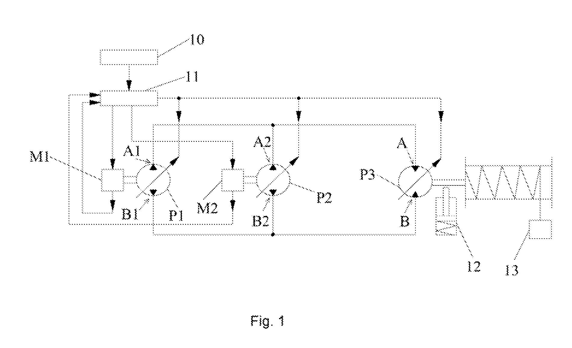
[0023]FIG. 1 is a schematic diagram illustrating a structure of a hydraulic control system in an embodiment of the present invention.

[0024]As shown in FIG. 1, the hydraulic control system in the embodiment of the present invention mainly comprises a first engine M1, and a first closed pump P1 connected thereto, a second engine M2 and a second closed pump P2 connected thereto, and a hydraulic motor P3. The hydraulic motor P3 serves as an actuator.

[0025]The first closed pump P1, the second closed pump P2 and the hydraulic motor P3 are connected in parallel. That is, a high pressure port A1 of the first dosed pump P1, a high pressure port A2 of the second closed pump P2 and port A of the hydraulic motor P3 are con...


PUM


Abstract

A hydraulic control system and a hydraulic control method are disclosed. The hydraulic control system comprises a first closed pump (P1) and a first engine (M1) connected with each other, a second closed pump (P2) and a second engine (M2) connected with each other, and a hydraulic motor (P3). The first closed pump (P1), the second closed pump (P2) and the hydraulic motor (P3) are connected in parallel. Compared with the prior art, the present hydraulic control system has advantages of wider engine model selection range, higher reliability and better micro-motion performance.

Description

TECHNICAL FIELD OF THE INVENTION[0001]The invention relates to the field of hydraulic technology, in particular to a hydraulic control system and a hydraulic control method.BACKGROUND OF THE INVENTION[0002]With the development of economy, super large tonnage cranes are applied broadly in production and construction, and a hydraulic control system of these super large tonnage cranes mainly includes an open loop system and a closed loop system. Specifically, a hydraulic control system of these super large tonnage cranes includes an open loop system with double pumps connected in parallel and a closed loop control system driven by a single pump.[0003]Since the closed loop control system driven by a single pump is driven only by a single pump, the single pump engine should meet the requirements of large tonnage cranes, thus bringing about limitation to model selection. Although the difficulty in model selection of super large tonnage engines may be solved by the open loop system with do...

Claims


Application Information

Patent Timeline
Patent Type & Authority Applications(United States)
IPC IPC(8): F15B15/18
CPCB60K5/08B60W10/06F15B7/006F15B2211/20546F15B2211/20561F15B15/18F15B2211/20576F15B2211/27F15B2211/761F15B2211/763F16H61/44F15B2211/20569
Inventor ZHAN, CHUNXINLIU, QUANZHANG, YUANSONG, CHUNYANGWANG, SHAOJUNYUAN, ZHIHUA
Owner ZOOMLION HEAVY IND CO LTD
Why Eureka
Try Eureka