Rotary engine

Inactive Publication Date: 2013-04-18
TATHUZAKI SEIKI
View PDF4 Cites 11 Cited by
  • Summary
  • Abstract
  • Description
  • Claims
  • Application Information

AI Technical Summary

Benefits of technology

The present invention provides a flywheel type of rotary engine that can achieve high output without using a movable piston head. This engine can perform the processes of intake-exhaust, compression, and explosive combustion without complex construction. The engine is also more compact and can obtain a large force with simple construction.

Problems solved by technology

However, in this kind of rotary engine, since the three vertices of the rotor come in frictional contact with the inner wall of the cylinder, there is a problem in that energy loss due to friction, durability and fuel efficiency of the engine become worse than in than in the case of a reciprocating engine, as well as construction is complicated making it difficult to produce.
However, the piston head of the rotor is made such that it is movable, so there is a problem in that construction is complicated.

Method used


Image

  • Rotary engine
  • Rotary engine
  • Rotary engine

Examples


Embodiment Construction

[0028]An embodiment of the present invention will be explained below with reference to the supplied drawings.

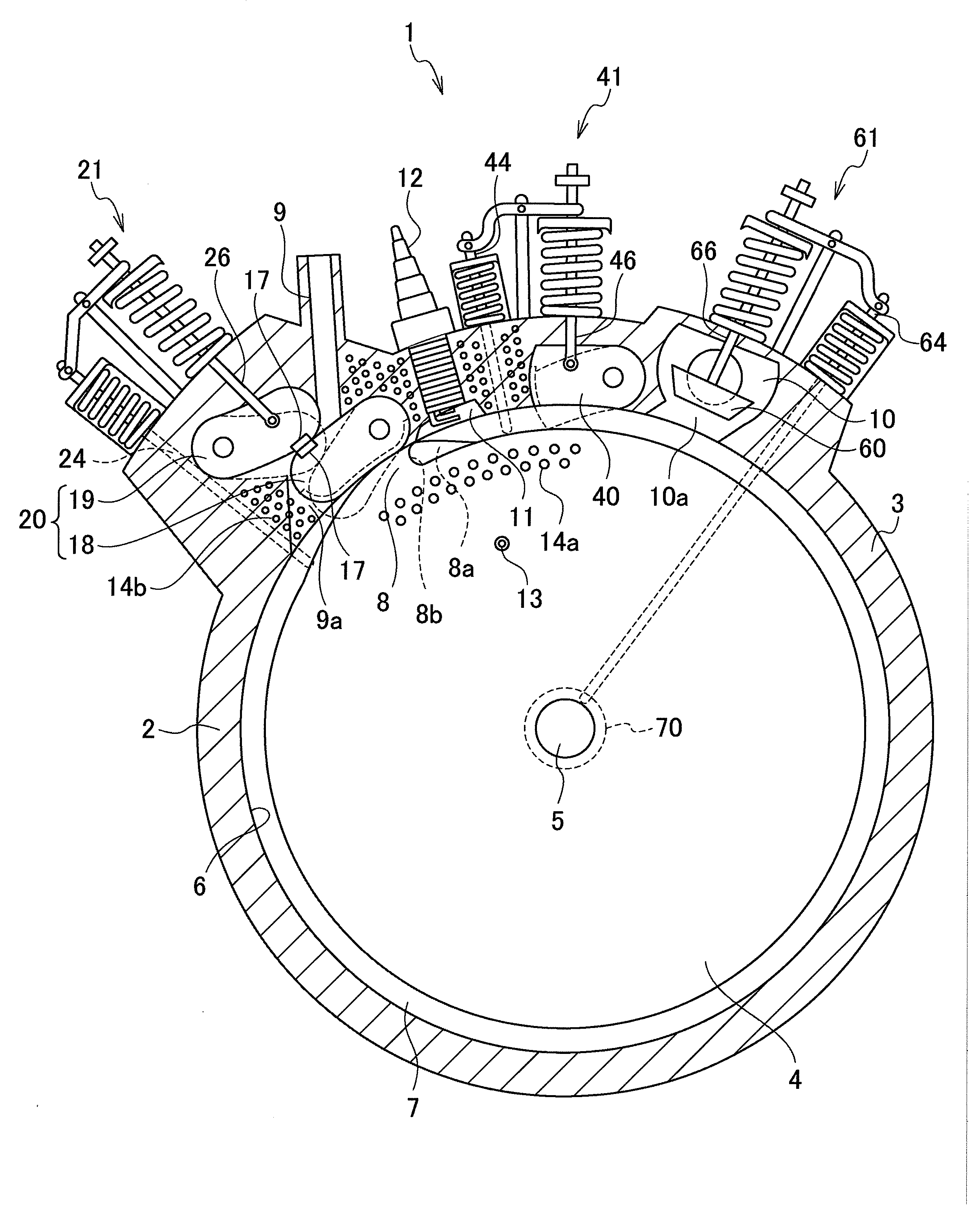
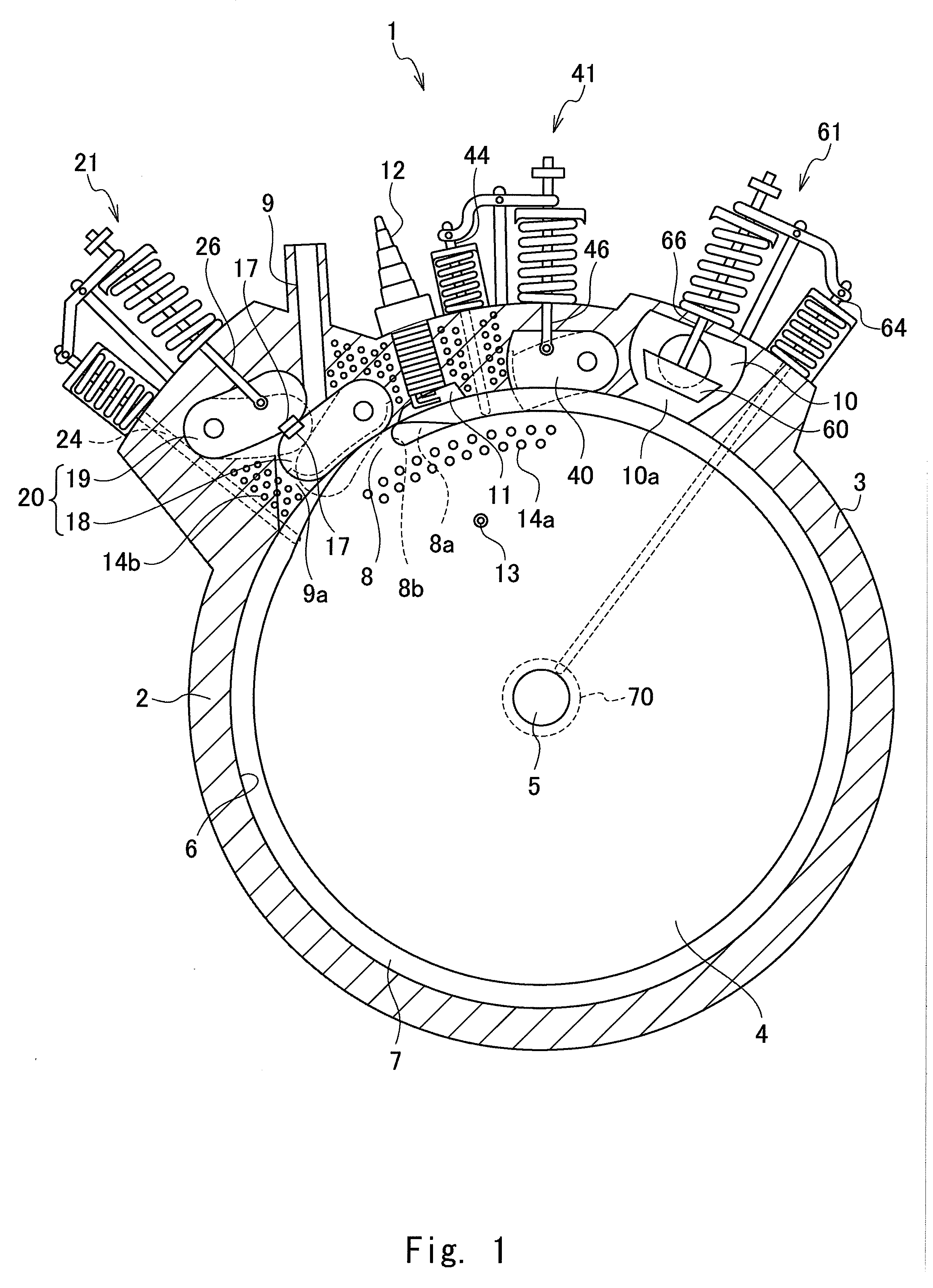
[0029]FIG. 1 is a cross-sectional drawing showing an embodiment of the rotary engine of the present invention. As shown in FIG. 1, the rotary engine 1 comprises a rotor housing 3 having a cylindrical-shaped cylinder 2, with a cylindrical-shaped flywheel rotor 4 being placed concentrically inside the cylinder 2. This rotor 4 is fixed to an output shaft 5 that passes through the center of the cylinder 3, forming a circular space 7 between the outer surface of the rotor 4 and the inner wall 6 of the cylinder 2. A piston head 8 is integrally formed on part of the outer surface of the rotor 4, and that piston head 8 protrudes outward in a hill shape toward the circular space 7 and comes in contact with the inner wall 6 of the cylinder 2. A concave section 8a having a vertical wall 8b in the radial direction of the rotor is formed in the portion on the upstream side in the rotation...


PUM


Abstract

A rotary engine that performs intake-exhaust, compression and explosive combustion without having moving piston heads in the rotor, is capable of obtaining large output with simpler construction. A flywheel rotor is arranged inside a cylinder that is inside a housing of a rotary engine, and is integrated into a single unit with a piston head that comes in contact with the inner wall. Direction of rotation of the rotor, An exhaust valve, an explosion pressure stopper valve and a fuel-intake closing valve are provided in the cylinder, Each of these valves operate via active pins that are engaged in guide grooves on the outer surface of the rotor and a guide groove on a cam of the output shaft, to execute the intake-exhaust, compression and explosive combustion.

Description

BACKGROUND OF THE INVENTION[0001]The present invention relates to a rotary engine in which a cylindrical-shaped flywheel rotor is placed inside a cylinder.[0002]Conventionally, a rotary engine, in which a triangular-shaped rotor is placed inside a cylindrical-shaped cylinder with the three vertices of the rotor coming in contact with the inner wall of the cylinder as the rotor turns, has been known. However, in this kind of rotary engine, since the three vertices of the rotor come in frictional contact with the inner wall of the cylinder, there is a problem in that energy loss due to friction, durability and fuel efficiency of the engine become worse than in than in the case of a reciprocating engine, as well as construction is complicated making it difficult to produce.[0003]Therefore, the inventors of the present invention have invented several flywheel engines in which a cylindrical-shaped flywheel rotor is placed inside a cylindrical-shaped cylinder, with a circular space being ...

Claims


Application Information

Patent Timeline
IPC IPC(8): F02B53/00
CPCF01C1/46F01C21/0809F02B53/10F02B53/06Y02T10/17F01C21/18Y02T10/12
Inventor TATHUZAKI, SEIKI
Owner TATHUZAKI SEIKI
Why Eureka
Try Eureka