Method for operating an internal combustion engine

Inactive Publication Date: 2013-04-18
GABDULLIN RIVENER MUSAVIROVICH
View PDF2 Cites 6 Cited by
  • Summary
  • Abstract
  • Description
  • Claims
  • Application Information

AI Technical Summary

Benefits of technology

[0014]The technical result of the invention is to shift the point of transition of the change in overall volume of the combustion chambers, from an increase to a decrease and vice versa, f

Problems solved by technology

The known technical solution has a number of disadvantages:the need to blow air through the combustion chamber after the exhaust stroke reduces the efficiency of the engine.the engine cannot work with a homogenized fuel and air mixture in a compression ignition mode.increasing the 1:2 transmission ratio between the shafts complicates the design and reduces its reliability.
However, this solution also has disadvantages:the engine works by compressing air to such a degree that the fuel sprayed into it is

Method used


Image

  • Method for operating an internal combustion engine
  • Method for operating an internal combustion engine
  • Method for operating an internal combustion engine

Examples


Embodiment Construction

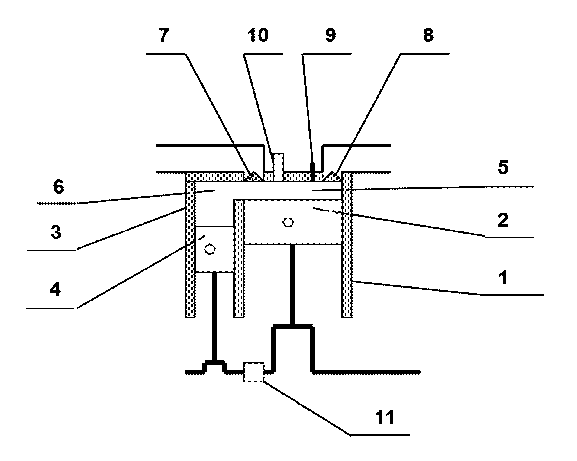
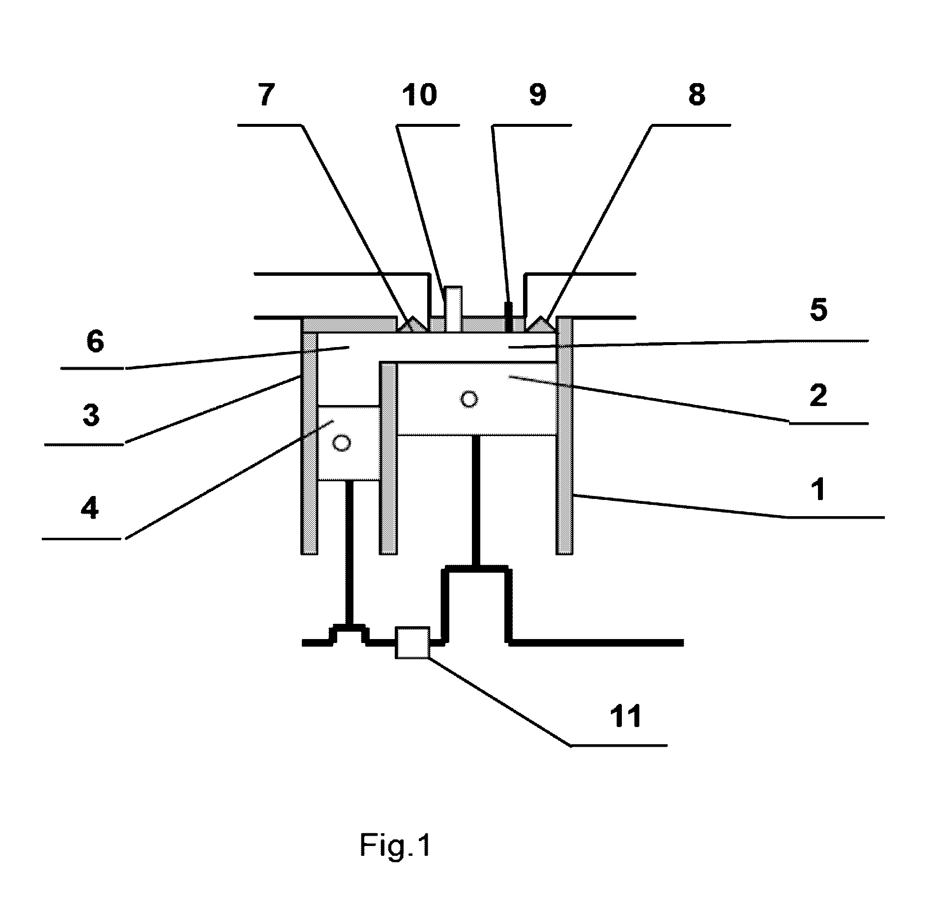
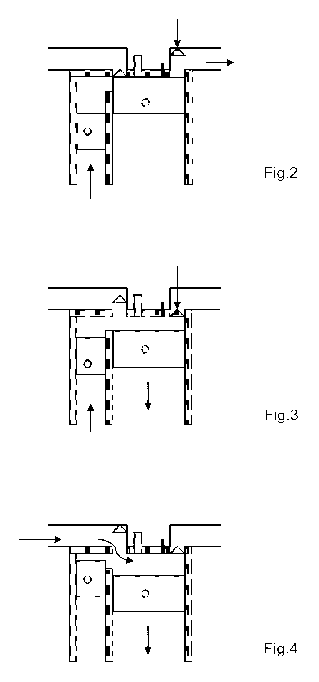
[0032]The invention being specified is realized in an internal combustion engine (FIG. 1) composed of a main cylinder 1, inside which there is a main piston 2, and an auxiliary cylinder 3, inside which there is an auxiliary piston 4. The main piston 2 and the main cylinder 1 form the combustion chamber 5, while the auxiliary piston 4 and auxiliary cylinder 3 form the combustion chamber 6, which are joined together and form a common combustion chamber in the upper part of the cylinders 1 and 3. In the common combustion chamber are installed the admission shutoff element 7, the exhaust shutoff element 8, the injector 9 and the spark plug 10. The crankshafts of both pistons are joined together by a rotation phase shift mechanism 11. Thanks to the presence of the auxiliary piston 4, whose crankshaft lags in rotation phase behind the crankshaft of the main piston, the points of transition of the change in overall volume of the combustion chambers 5 and 6, from increase to decrease and vi...


PUM


Abstract

The invention relates to engine building, and specifically to reciprocating internal combuston engines. The technical result of the invention consists in simplifying the design, the possibility of monitoring and regulating the moment of self-ignition of a homogenized fuel-air mix, and reducing the specific flow rate of the fuel. The method for operating an internal combustion engine consists in feeding a charge to the combustion chamber of a main cylinder and an auxiliary cylinder which are connected to one another and have different diameters, and in which the pistons are arranged. The piston of the auxiliary cylinder is delayed in accordance with the shaft rotation phase with respect to the piston of the main cylinder and as the piston of the main cylinder reaches the upper dead center thereof, when the majority of the charge is located in the auxiliary cylinder, and the charge to the piston of the auxiliary cylinder is boosted. The piston of the main cylinder is used to compress the mix without bringing said mix to self-ignition and therefore preparing said mix for subsequent rapid ignition, while the piston of the auxiliary cylinder is used to boost the compressed homogenized fuel-air mix, and said mix is brought to the temperature and pressure in the combustion chamber prior to compression self-ignition of the mix.

Description

FIELD OF TECHNOLOGY[0001]The invention relates to engine design, specifically, to reciprocating internal combustion engines.PRIOR ART[0002]There is known a twin reciprocating internal combustion engine (RF patent No. 2078963 of 7 Jun. 1994) containing two cylinders with a common combustion chamber, two crankshafts joined to each other by a 1:2 transmission, and when one piston is at its upper dead center the other is advanced by 45 angular degrees, or close to that, from its upper dead center. The working volumes of the cylinders are equal.[0003]The known technical solution has a number of disadvantages:[0004]the need to blow air through the combustion chamber after the exhaust stroke reduces the efficiency of the engine.[0005]the engine cannot work with a homogenized fuel and air mixture in a compression ignition mode.[0006]increasing the 1:2 transmission ratio between the shafts complicates the design and reduces its reliability.[0007]The closest to the invention in technical esse...

Claims


Application Information

Patent Timeline
IPC IPC(8): F02B75/04
CPCF02B19/06F02B41/00F02B41/04F02B75/04Y02T10/125F02B33/22F02B41/06F01B7/16F02B75/28Y02T10/12
Inventor GABDULLIN, RIVENER MUSAVIROVICH
Owner GABDULLIN RIVENER MUSAVIROVICH
Why Eureka
Try Eureka