Laser apparatus for welding

a laser welding and welding technology, applied in the direction of soldering apparatus, manufacturing tools,auxillary welding devices, etc., can solve the problems of welding portion breakage, increased initial investment cost, and long working hours

Inactive Publication Date: 2013-04-18
HYUNDAI MOTOR CO LTD +1
View PDF44 Cites 11 Cited by
  • Summary
  • Abstract
  • Description
  • Claims
  • Application Information

AI Technical Summary

Benefits of technology

[0016]The present invention has been made in an effort to provide a laser apparatus for welding having advantages of reducing manufacturing cost, shortening working hours, and enhancing productivity by enabling of brazing or laser welding that joins two joining members or panels through one apparatus.
[0021]In one or more exemplary embodiments of the present invention, the laser apparatus further includes a roller unit adapted to apply pressure to an upper portion of the joining members so as to control a gap between the joining members when laser welding the joining members.
[0032]In one or more exemplary embodiments of the present invention, the method further includes applying pressure to an upper portion of the joining members so as to control a gap between the joining members when laser welding the joining members.

Problems solved by technology

Therefore, breakage of the welding portion can occur.
Therefore, initial investment cost can increase.
Therefore, working hours are very long.
Because the brazing and the welding cannot be performed by one laser apparatus, manufacturing cost can increase.

Method used


Image

  • Laser apparatus for welding
  • Laser apparatus for welding
  • Laser apparatus for welding

Examples


Embodiment Construction

[0039]An exemplary embodiment of the present invention will hereinafter be described in detail with reference to the accompanying drawings.

[0040]Exemplary embodiments described in this specification and drawings are just exemplary embodiments of the present invention. It is to be understood that there can be various modifications and equivalents included in the spirit of the present invention at the filing of this application.

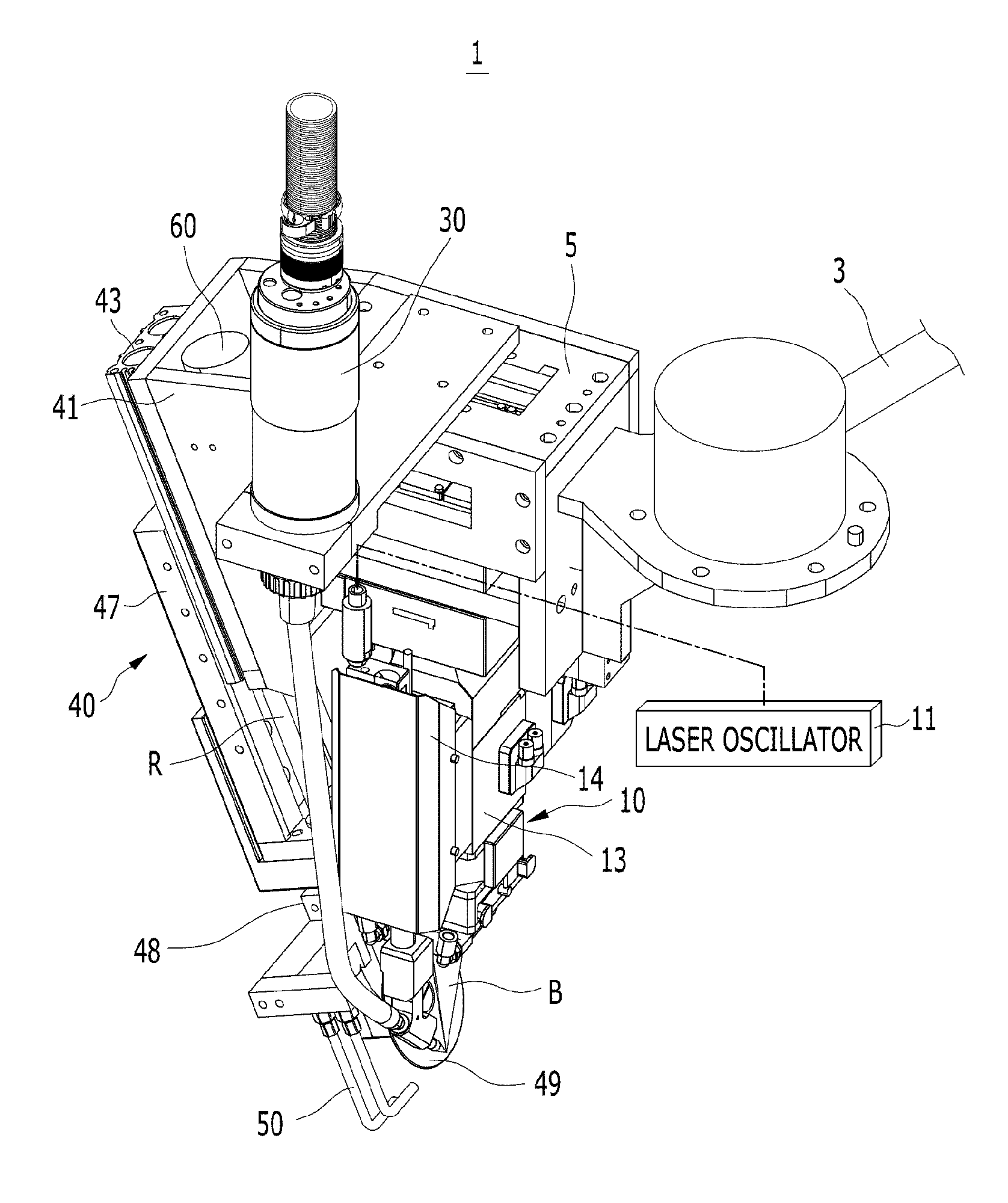
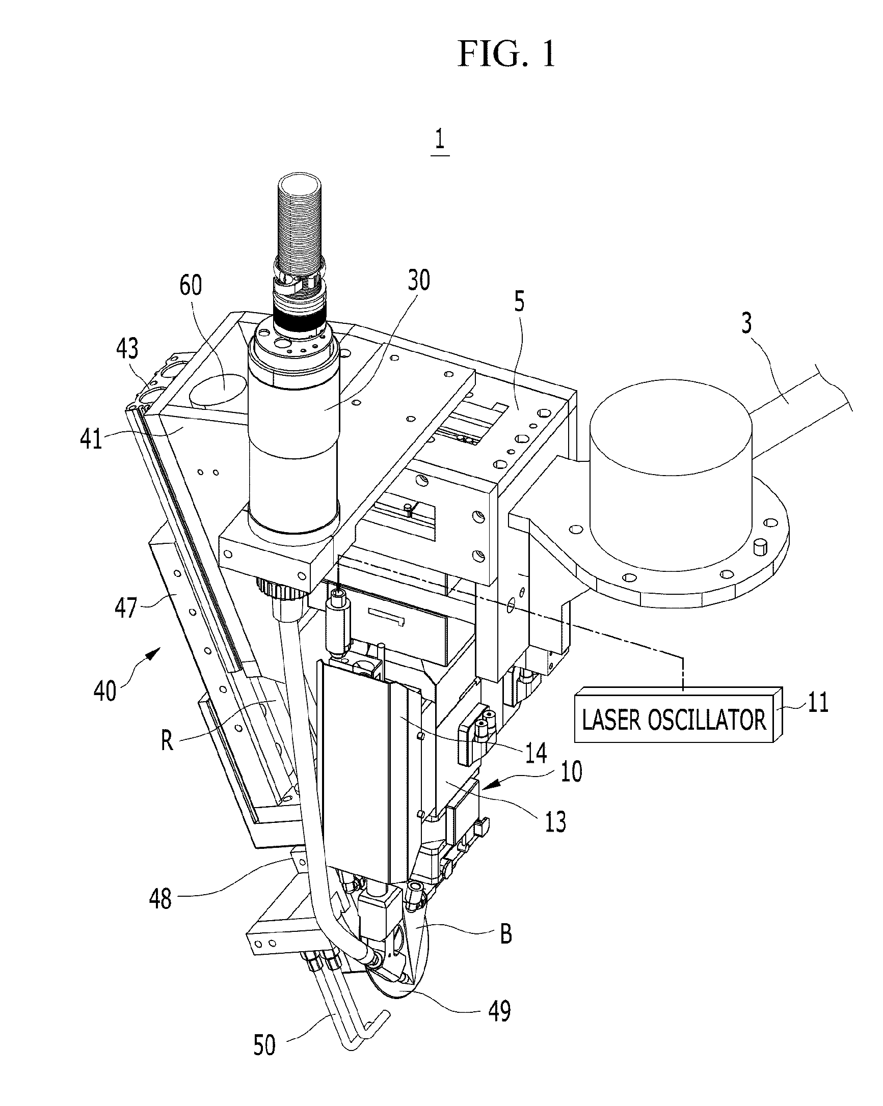
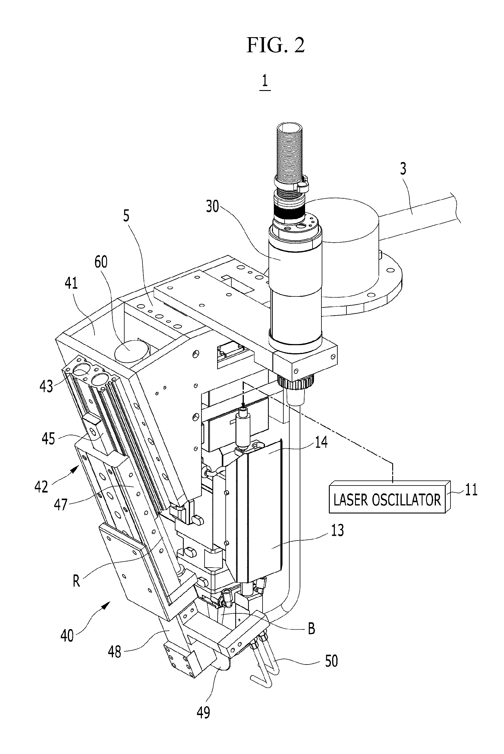
[0041]FIG. 1 is a perspective view of a laser apparatus for welding according to an exemplary embodiment of the present invention; FIG. 2 is another perspective view of a laser apparatus for welding according to an exemplary embodiment of the present invention; and FIG. 3 is a cross-sectional view of a laser optic head applied to a laser apparatus for welding according to an exemplary embodiment of the present invention.

[0042]Referring to the drawings, a laser apparatus 1 for welding according to an exemplary embodiment of the present invention enables of brazi...


PUM

PropertyMeasurementUnit
sizeaaaaaaaaaa
pressureaaaaaaaaaa
lengthaaaaaaaaaa

Abstract

A laser apparatus for welding is disclosed. The laser apparatus includes: a laser optic head adapted and configured to modify a spot size of a laser beam oscillated by a laser oscillator and to project the laser beam into a joining portion of joining members, wherein the laser optic head is adapted and configured to modify the spot size to selectively perform brazing or welding. A method of selectively brazing or welding according to one or more exemplary embodiments of the present invention includes: providing a laser apparatus of as described herein; and actuating the laser optic head to modify the spot size of the laser beam and project the laser beam into the joining portion of the joining members to selectively perform brazing or welding.

Description

CROSS-REFERENCE TO RELATED APPLICATION[0001]This application claims priority to and the benefit of Korean Patent Application No. 10-2011-01 04654 filed in the Korean Intellectual Property Office on Oct. 13, 2011, the entire contents of which are incorporated herein by reference.FIELD OF THE INVENTION[0002]The present invention relates to a laser apparatus for welding. More particularly, the present invention relates to a laser apparatus for welding that enables brazing or laser welding that joins two joining members or panels by using a laser beam through one apparatus.BACKGROUND OF THE INVENTION[0003]Recently, a laser beam is increasingly used in cutting, welding, and heat treatment of metal members due to cost reduction, factory automation, and quality improvement.[0004]Primary issues required for applying the laser beam are such that energy distribution of the laser beam is uniformized, laser output is controlled so as to maintain a constant heat treatment temperature, shooting s...

Claims


Application Information

Patent Timeline
Patent Type & Authority Applications(United States)
IPC IPC(8): B23K26/073B23K1/005B23K26/20B23K3/06B23K26/142B23K26/21
CPCB23K1/0056B23K26/023B23K26/03B23K26/046B23K31/125B23K26/1405B23K26/20B23K26/203B23K26/0643B23K26/037B23K26/142B23K26/211B23K26/24B23K26/346B23K26/073B23K9/124B23K37/0211B23K26/032B23K26/14B23K26/206B23K26/21B23K26/702B23K20/008B23K26/0648B23K26/0869
Inventor OH, KWANG MIN
Owner HYUNDAI MOTOR CO LTD
Why Eureka
Try Eureka