
Sheetless Backlight Module, A Light Guide Plate for the Sheetless Backlight and Manufacturing Method Thereof

a technology of backlight module and light guide plate, which is applied in the direction of manufacturing tools, lighting and heating apparatus, instruments, etc., can solve the problems of reducing the light utilization efficiency of display devices, and reducing the thickness of backlight modules, so as to reduce the cost of backlight module production and improve light utilization efficiency. , the effect of reducing the thickness of the backlight modul

Active Publication Date: 2013-04-18
AU OPTRONICS CORP
View PDF1 Cites 14 Cited by
  • Summary
  • Abstract
  • Description
  • Claims
  • Application Information

AI Technical Summary

Benefits of technology

The present invention provides a backlight module and a light guide plate that improve the efficiency of using light. Additionally, the light guide plate reduces the cost and thickness of the backlight module.

Problems solved by technology

In addition, accompanying the technology improvement in the display device industry as well as the user demands, display devices are getting smaller and lighter.
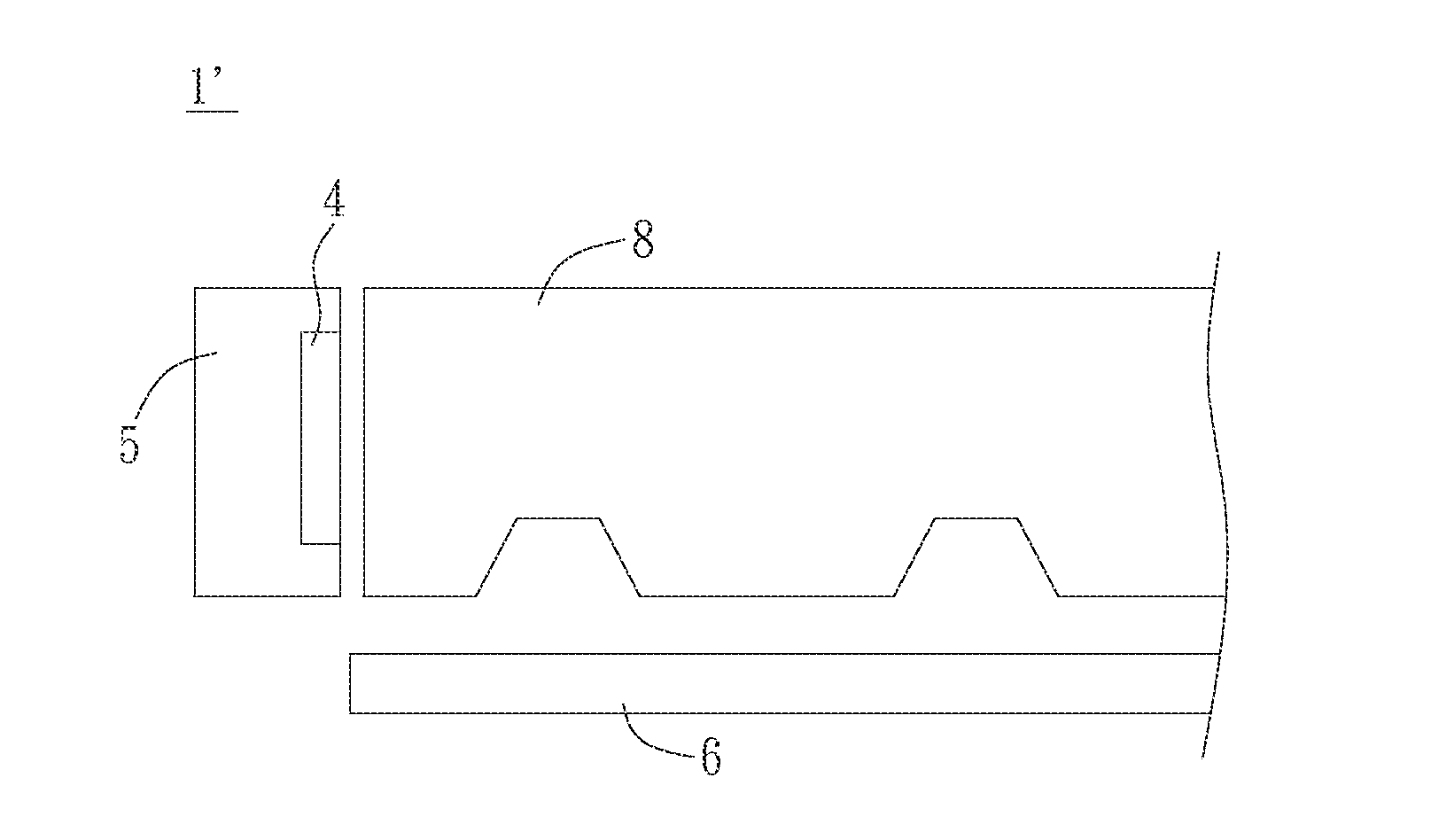
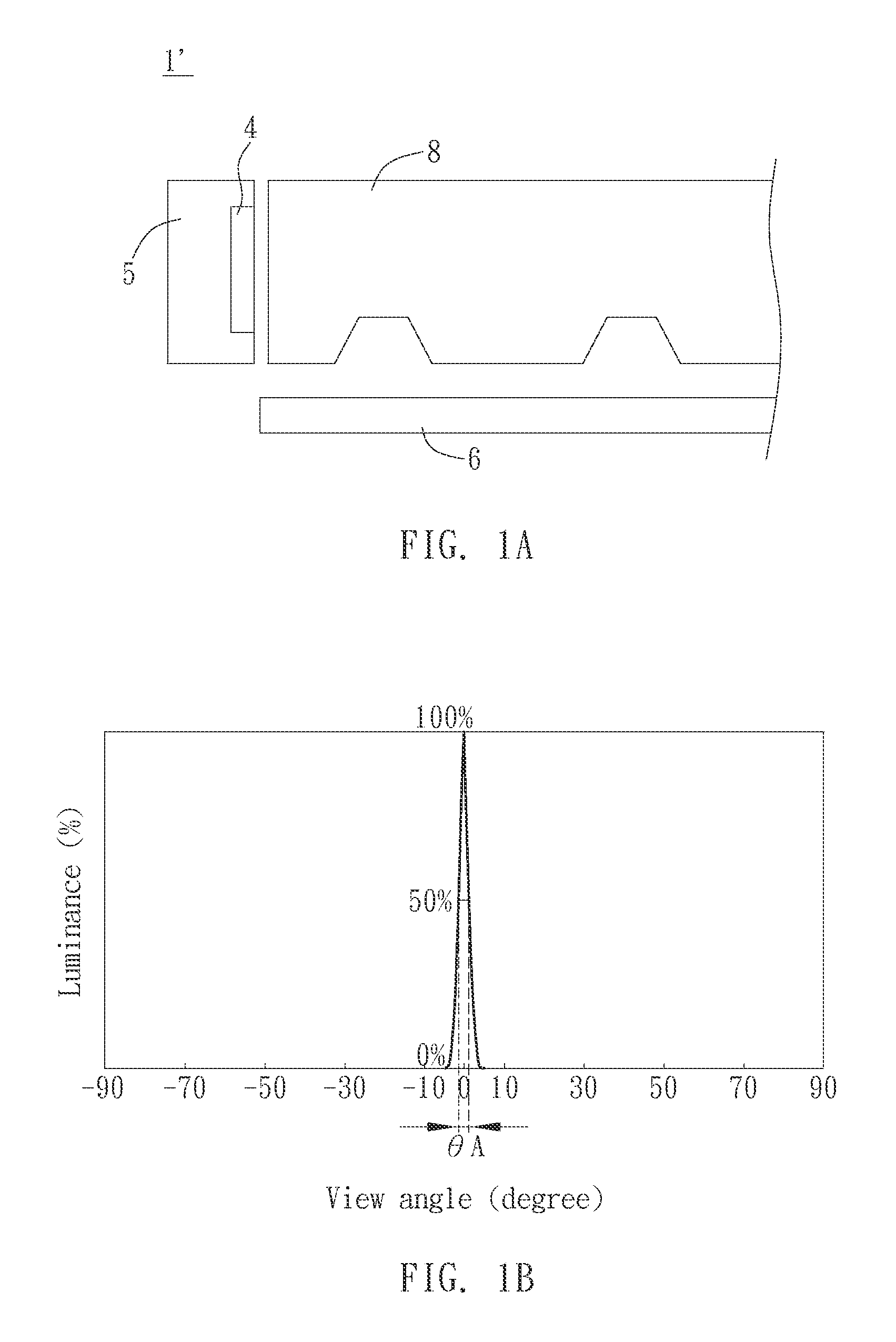
However, the sheetless backlight module 1′ has defects of hot spot and light ray which are concerned in visual quality.

Method used


Image

  • Sheetless Backlight Module, A Light Guide Plate for the Sheetless Backlight and Manufacturing Method Thereof
  • Sheetless Backlight Module, A Light Guide Plate for the Sheetless Backlight and Manufacturing Method Thereof
  • Sheetless Backlight Module, A Light Guide Plate for the Sheetless Backlight and Manufacturing Method Thereof

Examples


Embodiment Construction

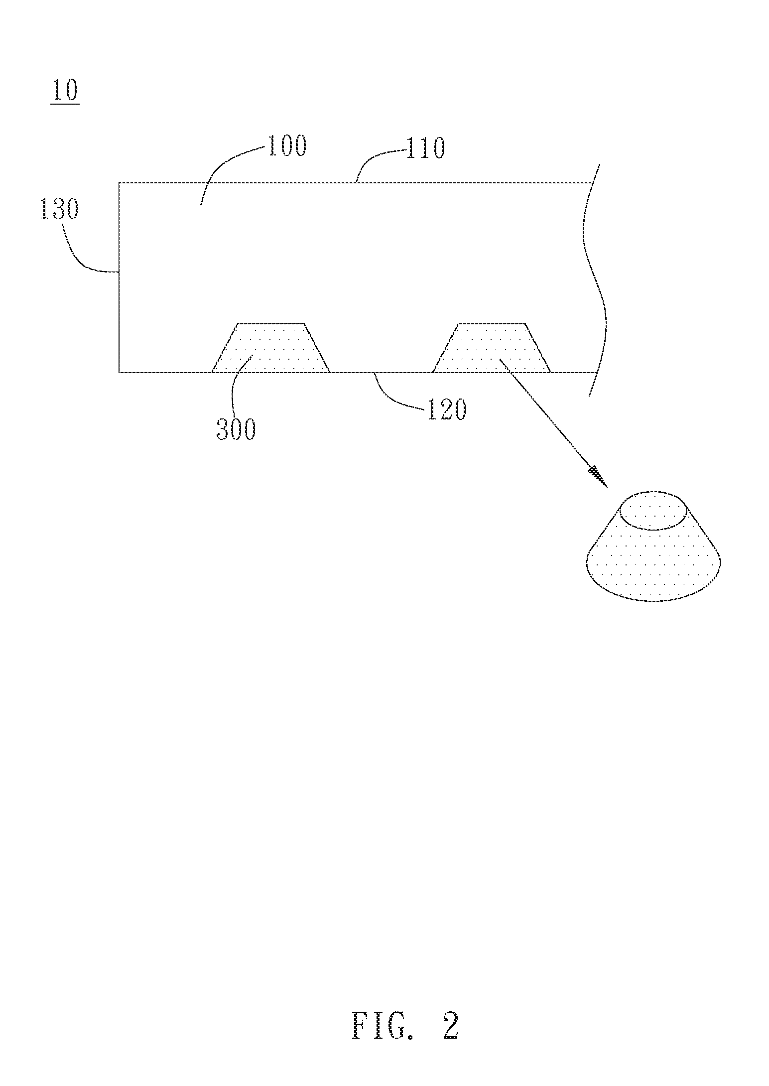
[0027]As the embodiment shown in FIG. 2, the light guide plate 10 of the present invention for a sheetless backlight module includes a body 100 and a plurality of light-scattering units 300. The body 100 includes a light-exiting face 110, a bottom 120 located opposite to the light-exiting face 110, and a light-entering end 130 located on one side of the light-exiting face 110 and the bottom 120 and connected to the light-exiting face 110 and the bottom 120. When the light guide plate 10 is used in the backlight module (described later), the light emitted by the light source enters the body 100 through the light-entering end 130. The light preferably leaves the light guide plate 10 from the light-exiting face 110 and then enters such as a display panel. The light-entering end 130 can be located on one side or two opposite sides of the body 100. The plurality of light-scattering units 300 are composed of material(s) different from material(s) of the body 100 and have optical character...


PUM

PropertyMeasurementUnit
diameteraaaaaaaaaa
acute angleaaaaaaaaaa
view angleaaaaaaaaaa

Abstract

A sheetless backlight module and a light guide plate thereof are provided. The light guide plate includes a body and a plurality of light scattering units. The body has a bottom and a plurality of microstructures formed on the bottom and recessed in the body from the bottom. The pluralities of light scattering units are disposed in a plurality of spaces formed due to the plurality of microstructures recessed in the body. A manufacturing method of the light guide plate mentioned above includes forming the plurality of microstructures on the bottom of the body; preparing a fluid solution containing at least a diffusive reflective material; distributing the fluid solution on the bottom; driving the fluid solution to flow into the microstructures; removing the part of the fluid solution outside the microstructures; and solidifying the fluid solution to form the plurality of light scattering units.

Description

BACKGROUND OF THE INVENTION[0001]1. Field of the Invention[0002]The present invention generally relates to a sheetless backlight module and a design of a light guide plate for the sheetless backlight module. Particularly, the present invention relates to a sheetless backlight module having a wider range of light-exiting angle and a light guide plate thereof.[0003]2. Description of the Prior Art[0004]Liquid Crystal Display (LCD) devices are extensively used in a variety of electrical devices such as computers, televisions, and mobile phones, wherein a light guide plate is used in a backlight module of the LCD device and is an essential element related to the light utilization efficiency. In addition to the light guidance and the control of exiting-light, the light guide plate is designed to elevate luminance and light uniformity, therefore improving the light utilization efficiency and optimizing the visual quality. In addition, accompanying the technology improvement in the display ...

Claims


Application Information

Patent Timeline
Patent Type & Authority Applications(United States)
IPC IPC(8): F21V8/00B23P17/04
CPCG02B6/0036Y10T29/49982G02B6/0065G02B6/0061
Inventor WU, YU-PINGFAN, FU-CHENGTSAI, WEI-HSIANGLO, WEI-HUNG
Owner AU OPTRONICS CORP
Learn More