Customer facing interface power cycling of wireless terminals

a wireless terminal and customer-facing technology, applied in the field of wireless terminals, can solve the problems of reducing affecting the service life of the wireless system, so as to improve the service life and minimize the disconnection event

Active Publication Date: 2013-04-18
TELSIMA
View PDF7 Cites 58 Cited by
  • Summary
  • Abstract
  • Description
  • Claims
  • Application Information

AI Technical Summary

Benefits of technology

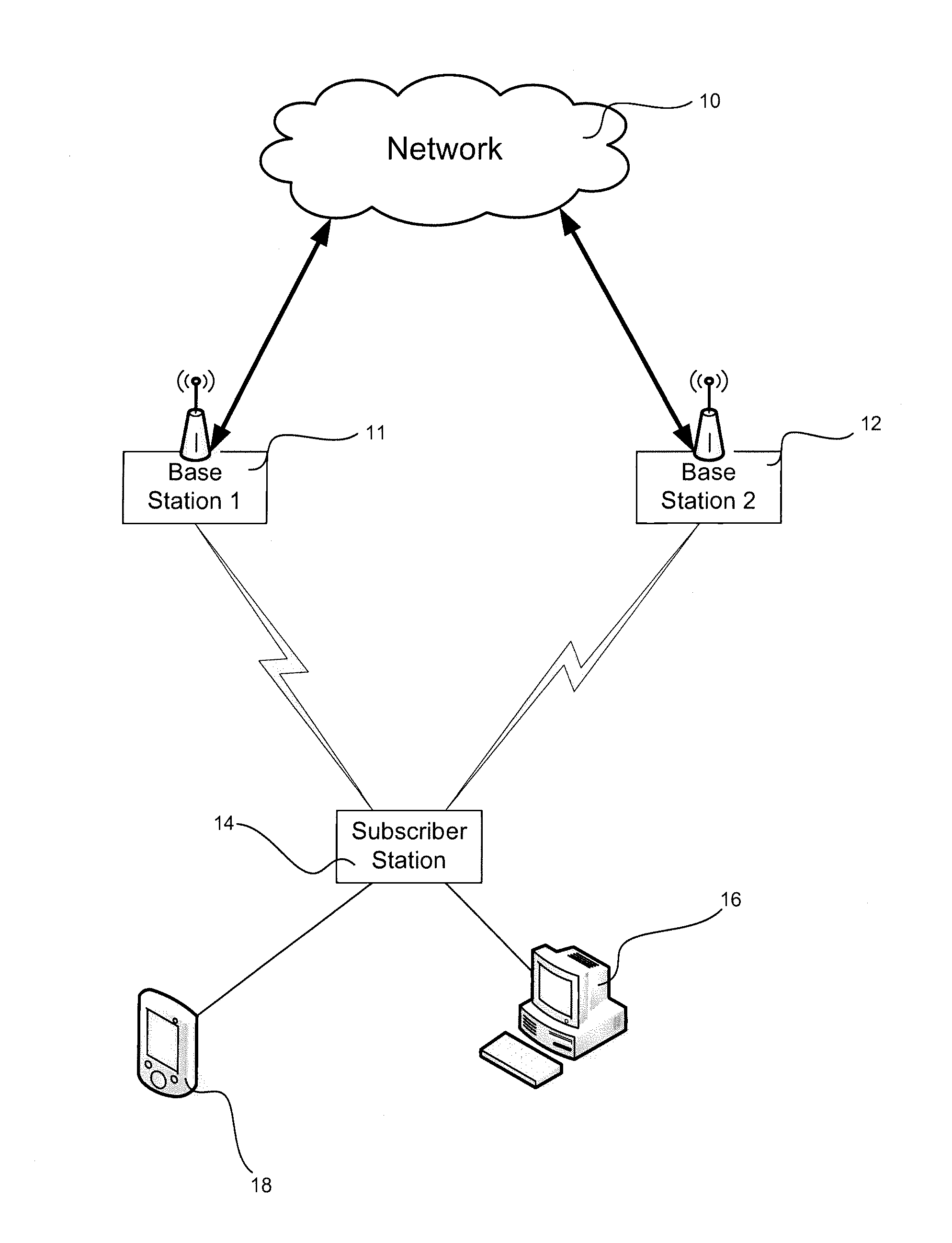
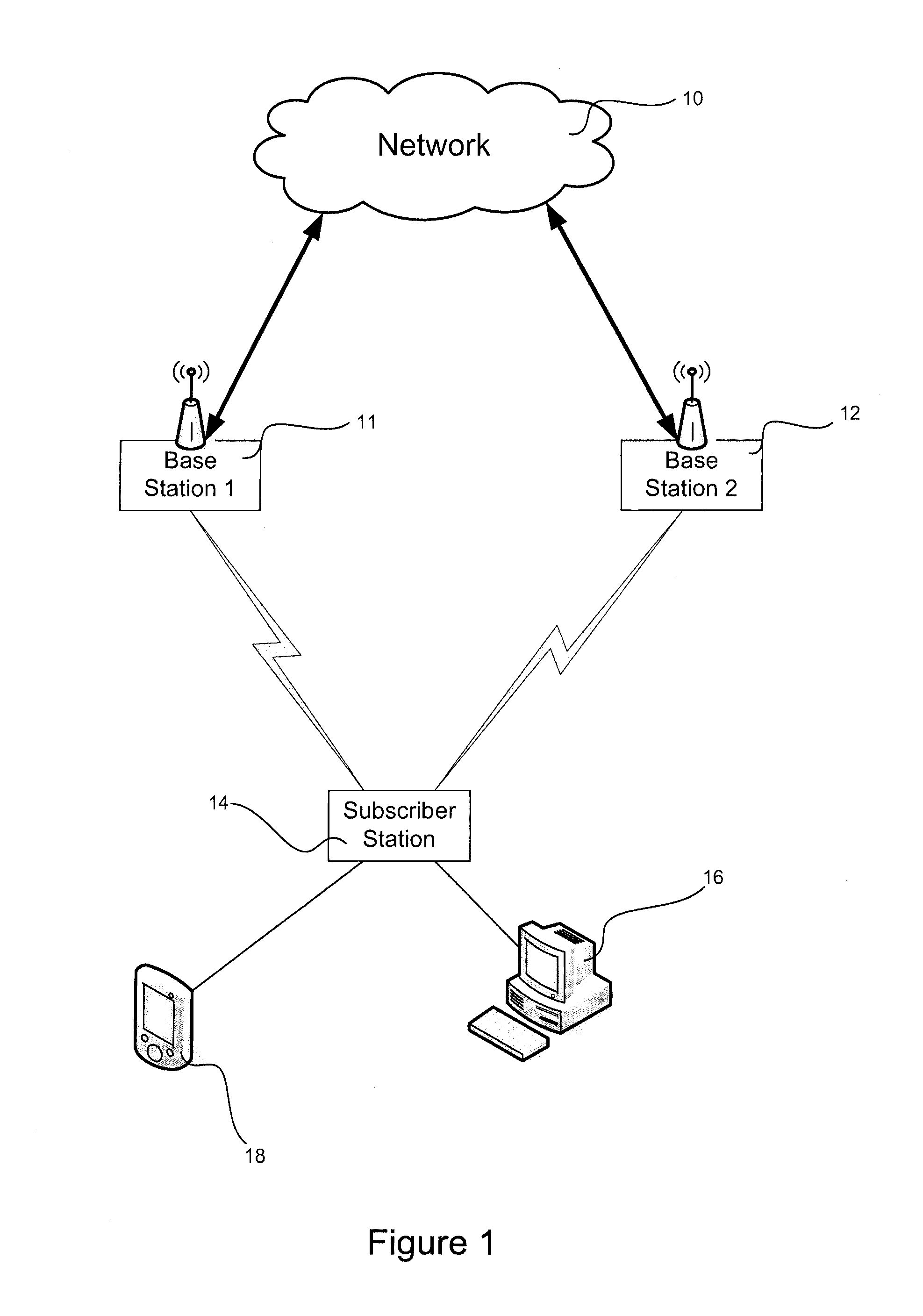
[0009]Certain embodiments of the invention enable the provision of enhanced service in wireless networks independent of subscriber station and CPE configuration and consistent with the characteristics of wired ADSL or cable network services. Accordingly, inherent differences between wireless and wired network designs are accommodated. These differences include the effects of unpredictable fading that can occur in wireless networks and which can cause a subscriber station to occasionally disconnect from one base station and reconnect to a different base station. Thus, in some embodiments, methods for controlling power cycling of CPE network interfaces are employed to minimize disconnection events.

Problems solved by technology

However, wireless systems are subject to network termination specific substantial signal fading and have the ability to connect using multiple network termination points.
However, the change of IP address is disruptive causing shutdown all network connections in use by application in the CPE.
Even when Dynamic DNS method is being used the DNS update is a slow process and takes hours and sometimes days to spread out in the Internet.
However, a new set of network topology problems will be observed.
For example, any broadcast packet will be repeated over all connected base stations, potentially causing a broadcast storm.
Malicious users could use broadcast storms to run theft of service and denial of service attacks.
Furthermore, identification and debugging of network problems is made difficult.
However, the initial IP address and VLAN assignment process can cause random distribution of IP addresses, resulting in an expanded and sometimes uncontrollable broadcast domain.

Method used


Image

  • Customer facing interface power cycling of wireless terminals
  • Customer facing interface power cycling of wireless terminals
  • Customer facing interface power cycling of wireless terminals

Examples


Embodiment Construction

[0017]Embodiments of the present invention will now be described in detail with reference to the drawings, which are provided as illustrative examples so as to enable those skilled in the art to practice the invention. Notably, the figures and examples below are not meant to limit the scope of the present invention to a single embodiment, but other embodiments are possible by way of interchange of some or all of the described or illustrated elements. Wherever convenient, the same reference numbers will be used throughout the drawings to refer to same or like parts. Where certain elements of these embodiments can be partially or fully implemented using known components, only those portions of such known components that are necessary for an understanding of the present invention will be described, and detailed descriptions of other portions of such known components will be omitted so as not to obscure the invention. In the present specification, an embodiment showing a singular compon...


PUM


Abstract

Systems and methods are described for configuring customer premises equipment in a wireless network in response to reconnection of subscriber station to a base station. A set of rules is provided that governs configuration of a network interface based in part on whether the interface connects to a different base station after reconnection. Reconfiguration may include cycling power of the network interface and the decision to cycle power may be based on network configuration determined after the loss of communication. This decision can be made after the loss of communication and after the network interface is reconnected to the wireless network through the same or a different base station. The rules may be processed by a combination of subscriber equipment, network interface and base station. Power may be cycled responsive to a message transmitted by the one base station to the network interface.

Description

CROSS-REFERENCE TO RELATED APPLICATIONS[0001]This application is a divisional application of U.S. Ser. No. 11 / 748,443, filed May 14, 2007, entitled “CUSTOMER FACING INTERFACE POWER CYCLING OF WIRELESS TERMINALS,” which claims priority to U.S. Ser. No. 60 / 747,162, filed May 12, 2006, entitled “CUSTOMER FACING INTERFACE POWER CYCLING OF WIRELESS TERMINALS,” both of which are incorporated by reference.BACKGROUND OF THE INVENTION[0002]1. Field of the Invention[0003]The present invention relates generally to wireless terminals and more particularly to the mobility of addressing in wireless networks.[0004]2. Description of Related Art[0005]Wireless Broadband Access (“WBA”) based systems have been designed to have operational characteristics that are indistinguishable from Cable or DSL methods of broadband access from the viewpoint of the customer. However, wireless systems are subject to network termination specific substantial signal fading and have the ability to connect using multiple ...

Claims


Application Information

Patent Timeline
Patent Type & Authority Applications(United States)
IPC IPC(8): H04W24/04H04W24/02
CPCH04L41/0806H04W36/0077H04W24/04H04W24/02
Inventor BESER, NURETTIN B.
Owner TELSIMA
Why Eureka
Try Eureka