Radio relay station apparatus and mobile terminal apparatus
- Summary
- Abstract
- Description
- Claims
- Application Information
AI Technical Summary
Benefits of technology
Problems solved by technology
Method used
Image
Examples
embodiment 1
[0035]A case will be described here with the present embodiment where the number of mobile terminal apparatuses under the subject cell is decided and transmission power is controlled based on this number of mobile terminal apparatuses.
[0036]FIG. 8 is a block diagram showing a schematic configuration of a radio relay station apparatus according to embodiment 1 of the present invention. The transmitting side of the radio relay station apparatus shown in FIG. 8 includes a data signal generation section 801, a channel coding section 802, a modulation section 803, a mapping section 804, a reference signal generation section 805, an IFFT (Inverse Fast Fourier Transform) section 806, and a CP (Cyclic Prefix) insertion section 807. Also, the receiving side of the radio relay station apparatus includes a CP removing section 808, an FFT (Fast Fourier Transform) section 809, a demapping section 810, an uplink transmission data demodulation section 811, a user terminal count deciding section 81...
embodiment 2
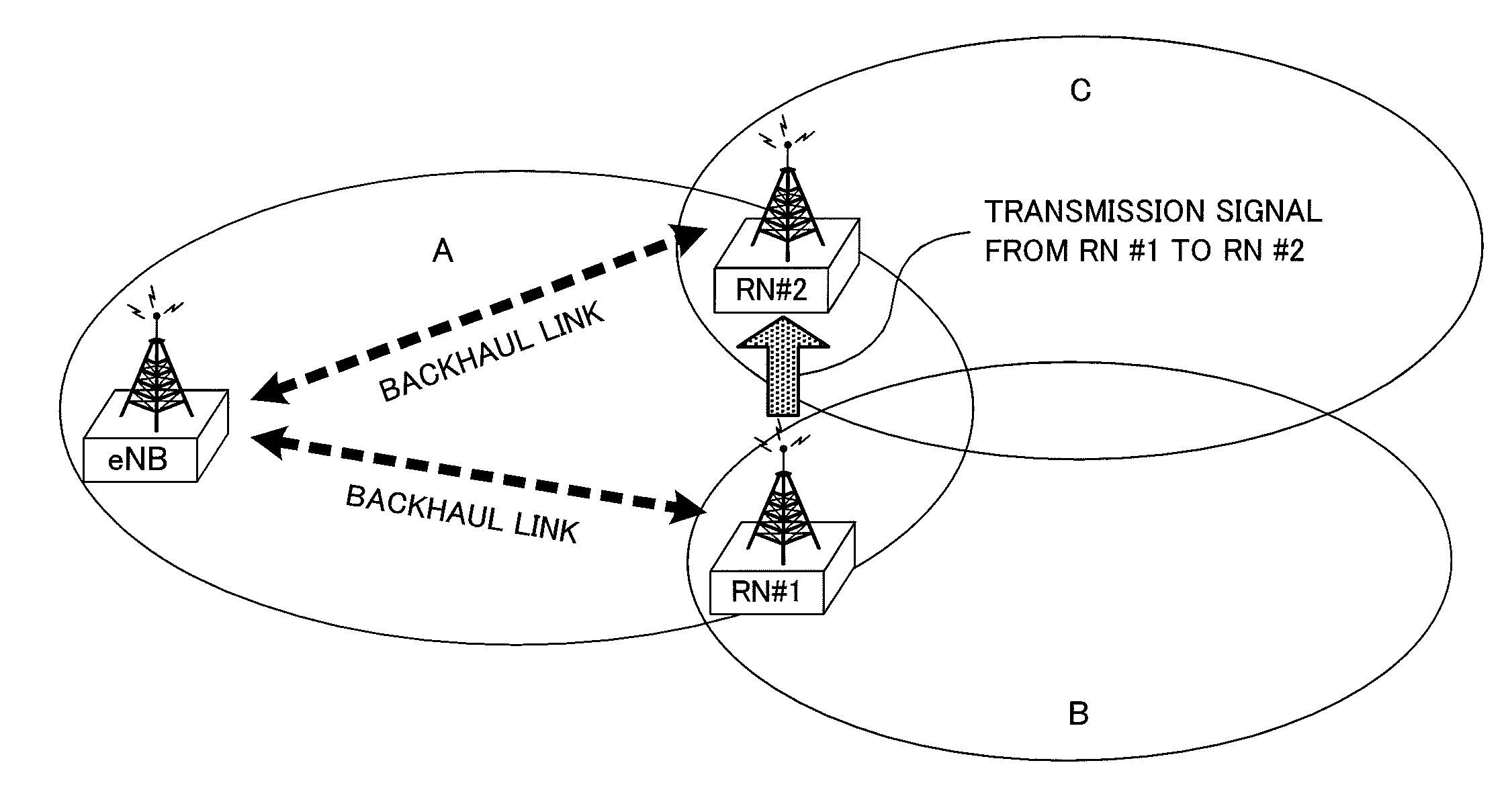
[0047]A case will be described here with the present embodiment where the received power of a signal from another radio relay station apparatus is measured and transmission power is controlled based on this received power. The configuration of mobile terminal apparatus according to the present embodiment is the same as the configuration shown in FIG. 9.
[0048]FIG. 10 is a block diagram showing a schematic configuration of a radio relay station apparatus according to embodiment 2 of the present invention. Parts in FIG. 10 that are the same as in FIG. 8 will be assigned the same codes as in FIG. 8 and their detailed to descriptions will be omitted. The radio relay station apparatus shown in FIG. 10 has a received power measurement section 814.
[0049]The received power measurement section 814 measures the received power of the signal from another RN (the signal from RN #1 to RN #2 in FIG. 5), and, comparing that received power and a predetermined number (threshold value), decides whether...
embodiment 3
[0053]A case will be described here with the present embodiment where the received power of the signal from a radio base station apparatus is measured and transmission power is controlled based on this received power. The configuration of a mobile terminal apparatus according to the present embodiment is the same as the configuration shown in FIG. 9, and the configuration of a radio relay station apparatus is the same as the configuration shown in FIG. 10.
[0054]The received power measurement section 814 measures the received power of the signal from an eNB (the signal from the eNB to RN #2 in FIG. 6), and, comparing that received power and a predetermined number (threshold value), decides whether the received power is higher or lower than the predetermined value. The received power measurement section 814 outputs the decided result to the transmission power control section 813.
[0055]The transmission power control section 813 controls transmission power based on the received power of...
PUM
 Abstract
Description
Claims
Application Information
 - R&D
- Intellectual Property
- Life Sciences
- Materials
- Tech Scout
- Unparalleled Data Quality
- Higher Quality Content
- 60% Fewer Hallucinations
Browse by: Latest US Patents, China's latest patents, Technical Efficacy Thesaurus, Application Domain, Technology Topic, Popular Technical Reports.
© 2025 PatSnap. All rights reserved.Legal|Privacy policy|Modern Slavery Act Transparency Statement|Sitemap|About US| Contact US: help@patsnap.com


