
Motor programming tool

Inactive Publication Date: 2013-04-18
NIDEC MOTOR CORP
View PDF13 Cites 10 Cited by
  • Summary
  • Abstract
  • Description
  • Claims
  • Application Information

AI Technical Summary

Benefits of technology

The present invention provides a motor programming tool that is simple to use and consistent in operation. The tool features a longer useful life than previous programming tools. The tool uses plungers that directly connect to motor terminals, making the connection quick and secure. Tool terminal elements are used to make the connection between the plungers and motor terminals, which can be easily replaced if needed. The circuitry in the tool includes a time-delay relay element that ensures the connection is secure before transmitting signals to the motor controller. The tool also provides power to the motor during programming.

Problems solved by technology

While prior art motor programming tools have been satisfactory in some respects, the required plugging and unplugging of the mating terminals has also presented drawbacks.
These established connection systems are time consuming and require significant insertion and separation force to connect and then remove the mating terminals and sockets.
As is generally known in the art, the mating terminals and sockets provided between the motor connection block and existing programming tools are not particularly suited for multiple plugging and unplugging operations during the life span of the components.
Such repeated plugging and unplugging operations can damage the components, rendering either the terminals of the motor connection block or the sockets of the programming tool (or both) unusable.
Since these sockets have traditionally been crimped, soldered, or otherwise permanently connected to wiring of the tool, such repair (requiring reconstruction of these permanent wiring connections just to replace damaged sockets) is time consuming and results in significant downtime in the useful life of the programming tool.
This results in greater uptime and a longer useful life of the inventive motor programming tool.

Method used


Image

  • Motor programming tool
  • Motor programming tool
  • Motor programming tool

Examples


Embodiment Construction

[0039]The present invention is susceptible of embodiment in many different forms. While the drawings illustrate, and the specification describes, certain preferred embodiments of the invention, it is to be understood that such disclosure is by way of example only. There is no intent to limit the principles of the present invention to the particular disclosed embodiments.

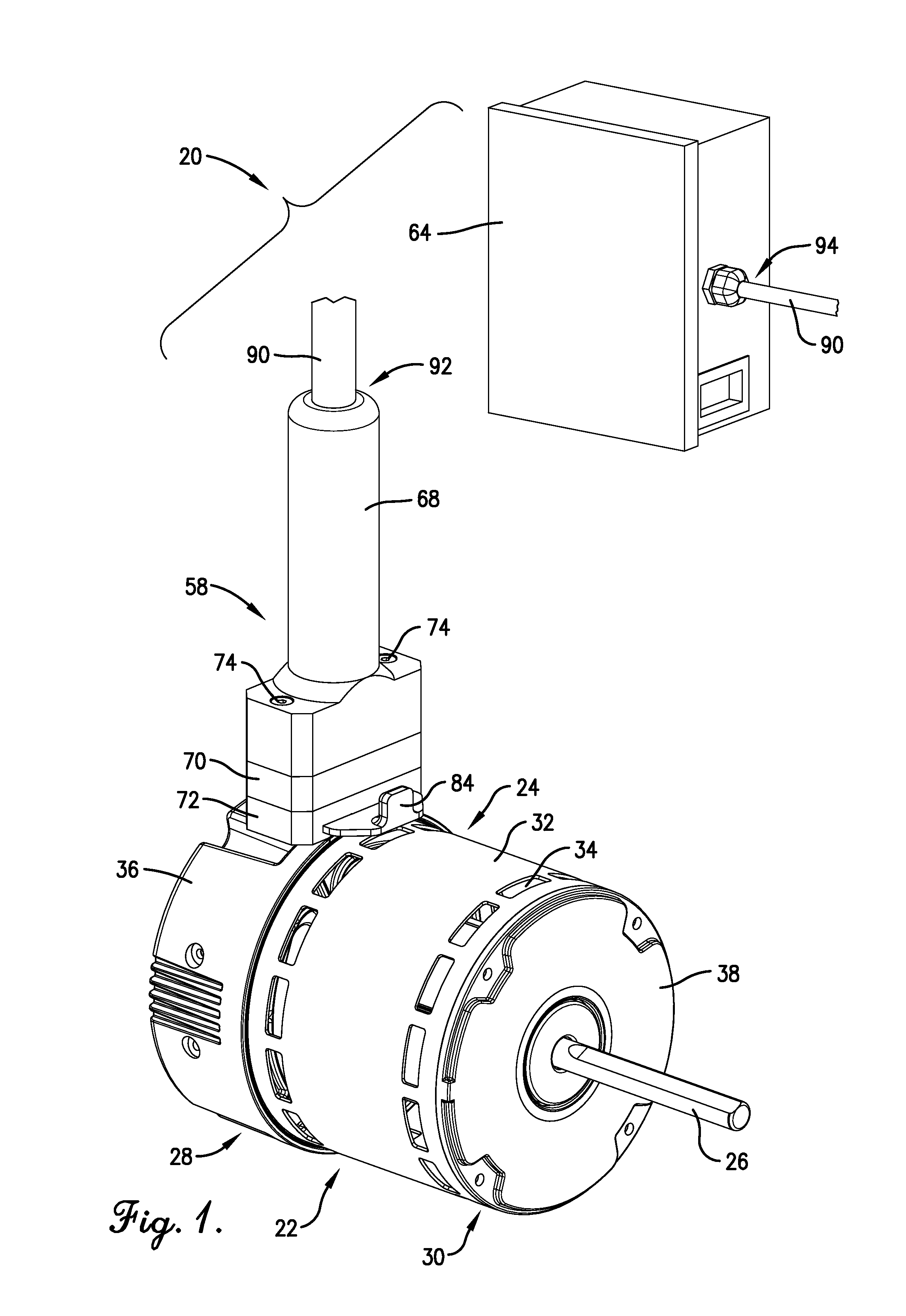
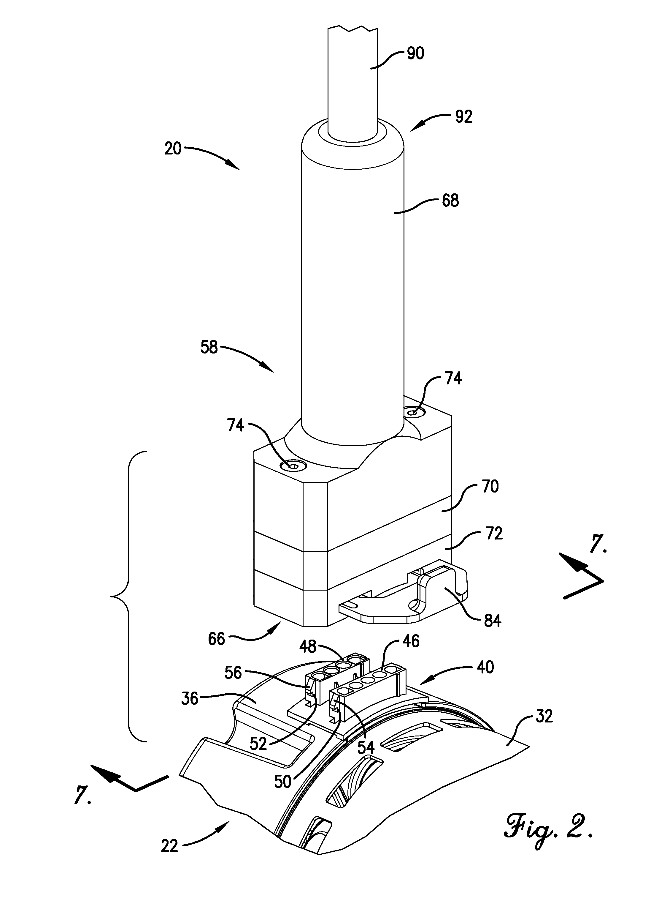
[0040]With initial reference to FIGS. 1-8, a motor programming tool 20 constructed in accordance with an embodiment of the present invention is depicted for temporarily associating with an electric motor 22.

[0041]As is generally customary, the motor 22 broadly includes a rotor assembly (not shown), rotatable about an axis, and a stator assembly (not shown). The rotor assembly and the stator assembly are both contained within an internal motor chamber that is defined by a motor case 24. As shown in FIG. 1, the rotor assembly includes an axially disposed shaft 26 that projects outwardly from one end of the motor case 2...


PUM


Abstract

A motor programming tool is disclosed for associating with a connection block of a motor and sending signals to a programmable controller of the motor, where the connection block includes a plurality of terminals coupled to the controller. The programming tool includes a tool body with an interface generally corresponding with the connection block of the motor, wiring operable to carry the signals, and a plurality of terminal connecting assemblies to associate with the motor terminals. The tool body includes a shiftable locking mechanism operable to selectively secure the tool body relative to the electrical connection block of the motor. The locking mechanism includes a pivotable latch moveable between an open position, wherein the connecting assemblies are freely moveable into and out of contact with the motor terminals, and a closed position, wherein at least a portion of the pivotable latch is in contact with the motor and the connecting assemblies are restricted from moving out of contact with the motor terminals.

Description

RELATED APPLICATIONS[0001]This non-provisional patent application is a continuation-in-part of earlier-filed U.S. patent application titled MOTOR PROGRAMMING TOOL, filed Aug. 4, 2011, and assigned application Ser. No. 13 / 198,531. This application claims priority benefit with regard to all common subject matter of the earlier-filed U.S. patent application. The earlier-filed application is hereby incorporated by reference in its entirety into the present application.BACKGROUND OF THE INVENTION[0002]1. Field of the Invention[0003]The present invention relates generally to a tool for programming electric motor controllers. More specifically, the present invention concerns a motor programming tool for temporarily associating with an electrical connection block of a motor to send electrical signals to a programmable controller of the motor.[0004]2. Discussion of the Prior Art[0005]Those of ordinary skill in the art will appreciate that electric motors typically include a controller that g...

Claims


Application Information

Patent Timeline
IPC IPC(8): H01R13/62
CPCH01R11/18H01R13/2421H01R13/512H01R13/15H01R13/62H01R13/639G05B24/02H01R2201/20
Inventor RASSOOLKHANI, PAYMANMODI, CHETAN O.GEILER, CHARLES L.PLOOF, JR., ROBERT J.
Owner NIDEC MOTOR CORP
Learn More