Heat pump

Active Publication Date: 2013-04-25
MITSUBISHI ELECTRIC CORP
View PDF9 Cites 68 Cited by
  • Summary
  • Abstract
  • Description
  • Claims
  • Application Information

AI Technical Summary

Benefits of technology

[0007]According to the present invention, there is no need to lower the pressure of the refrigerant used for defrosting to the suction temperature. Therefore, in the compressor, only the refrigerant used for heating that circulates in the main circuit needs to be raised from low pressure to high pressure, and as for the injected intermediate-pressure refrigerant in the two-phase gas-liquid state, its pressure only needs to be raise

Problems solved by technology

However, this defrosting method compromises indoor comfort

Method used


Image

  • Heat pump
  • Heat pump
  • Heat pump

Examples


embodiment 1

of the Invention

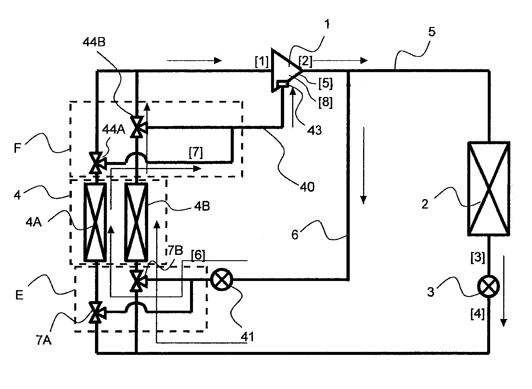
[0034]Hereinafter, Embodiment 1 of the present invention will be described with reference to the drawings. In the drawings, identical or equivalent portions are denoted by identical reference signs. FIG. 1 illustrates the refrigerant circuit of a heat pump according to Embodiment 1 of the present invention.

[0035]The refrigerant circuit of the heat pump has a main circuit in which a compressor 1, an indoor heat exchanger 2, a first flow rate control means (electronic expansion valve in this example) 3 that can open and close, and an outdoor heat exchanger 4 are sequentially connected by a main pipe 5. The outdoor heat exchanger 4 is divided into a plurality of parallel heat exchangers, which in this example are two parallel heat exchangers 4A and 4B. The main circuit where the outdoor heat exchanger 4 is arranged branches off into a plurality of (two in this example) portions of a parallel circuit in accordance with the number of parallel heat exchangers. Also, the ma...

embodiment 2

of the Invention

[0058]In Embodiment 2, instead of the configuration in Embodiment 1 in which a part of the refrigerant discharged from the compressor 1 is bypassed to flow into the outdoor heat exchanger 4, a compressor is additionally provided on the discharge side of the compressor 1 of Embodiment 1, and a part of the refrigerant discharged from the additionally provided compressor is bypassed to flow into the outdoor heat exchanger 4. Also, while the refrigerant that has been used for defrosting is injected into the compressor 1 in Embodiment 1, in Embodiment 2, the refrigerant that has been used for defrosting is merged at the main pipe between the compressor 1 and the additionally provided compressor.

[0059]FIG. 8 illustrates the refrigerant circuit of an air-conditioning device, as an example of a heat pump according to Embodiment 2 of the present invention. In FIG. 8, portions that are identical to those in FIG. 1 are denoted by identical reference signs.

[0060]The refrigerant ...

embodiment 3

of the Invention

[0071]FIG. 12 illustrates the refrigerant circuit of an air-conditioning device, as an example of a heat pump according to Embodiment 3 of the present invention. In FIG. 12, portions that are identical to those in FIG. 1 are denoted by identical reference signs. The air-conditioning device of Embodiment 3 basically includes the heat pump of Embodiment 1 illustrated in FIG. 1, and is further configured to be able to also perform a cooling operation. That is, the air-conditioning device is provided with a four-way valve 60 that supplies the gas refrigerant discharged from the compressor 1 to either the outdoor heat exchanger 4 or indoor heat exchanger 2.

[0072]As illustrated in FIG. 12, the air-conditioning device according to Embodiment 3 includes an outdoor unit A, an indoor unit B, and a first pipe 5a and a second pipe 5b that connect those units. The air-conditioning device is a multi-type air-conditioning unit in which a plurality of indoor units are connected to a...


PUM


Abstract

A first bypass pipe has one end connected to a main pipe extending from a compressor to an indoor heat exchanger, and its other end branched off into parts that are each connected to the main pipe on an inlet side of an outdoor heat exchanger, and a second bypass pipe has one end connected to an injection port communicating with the compression chamber of the compressor in which compression is taking place and its other end branched off into parts that are each connected to the main pipe on an outlet side of the outdoor heat exchangers. During a defrosting operation that removes frost on the outdoor heat exchangers, a part of the refrigerant discharged from the compressor is supplied from the first bypass pipe to the outdoor heat exchanger to be defrosted, and is then passed through the second bypass pipe and injected from the injection port of the compressor.

Description

TECHNICAL FIELD[0001]The present invention relates to a heat pump.BACKGROUND ART[0002]In heat pumps according to the related art, to remove frost n on an outdoor heat exchanger that serves as an evaporator during a heating operation, a defrosting operation is performed by reversing the refrigeration cycle. However, this defrosting method compromises indoor comfort because heating is stopped during the defrosting operation. Accordingly, as a technology that enables a simultaneous heating operation and defrosting operation, there is a heat pump in which an outdoor heat exchanger is divided into a plurality of parallel heat exchangers with reference to a refrigerant flow diversion path, and a bypass that bypasses a discharge gas from a compressor, and a solenoid opening and closing valve that controls the bypass state are provided in each of those parallel heat exchangers (see, for example, Patent Literature 1). In this heat pump, a part of the refrigerant from the compressor is caused...

Claims


Application Information

Patent Timeline
IPC IPC(8): F25B47/02F25B30/02
CPCF25B1/10F25B5/02F25B13/00F25B41/04F25B47/025F25B2400/0403F25B2400/0411F25B2400/13F25B30/02F25B47/022F25B41/20
Inventor WAKAMOTO, SHINICHITAKENAKA, NAOFUMIMORIMOTO, OSAMUKOGE, HIROFUMISHINOZAKI, KAZUYOSHIKAWAGOE, TOMOKAZU
Owner MITSUBISHI ELECTRIC CORP
Why Eureka
Try Eureka