Ultrasonic sensor

Active Publication Date: 2013-04-25
RISO KAGAKU CORP
View PDF9 Cites 10 Cited by
  • Summary
  • Abstract
  • Description
  • Claims
  • Application Information

AI Technical Summary

Benefits of technology

The invention is designed to improve ultrasonic sensors by reducing the impact of diffraction waves without the need to space apart the transmitting and receiving horns. This results in a longer detection range and increased accuracy of the sensor.

Problems solved by technology

In particular, the ultrasonic sensor is used for the detection of an object to be detected, which a photosensor is not good at detecting, such as the detection of a transparent or semi-transparent film, such as an ultralight paper or a master for a stencil printing plate, the detection of the position of a paper, both sides of which are printed in black, or the detection of the liquid level of ink or the like, in the field of printing, for example.
At this time, because the transmitting horn and the receiving horn are arranged side by side each facing to the same direction, a diffraction wave generated at an edge of an opening of the transmitting horn may be further diffracted at an edge of an opening of the receiving horn and received by the reception element, thereby reducing the detection accuracy of the object to be detected.

Method used


Image

  • Ultrasonic sensor
  • Ultrasonic sensor
  • Ultrasonic sensor

Examples


Embodiment Construction

[0023]Several embodiments of the present invention will be described below with reference to the accompanying drawings.

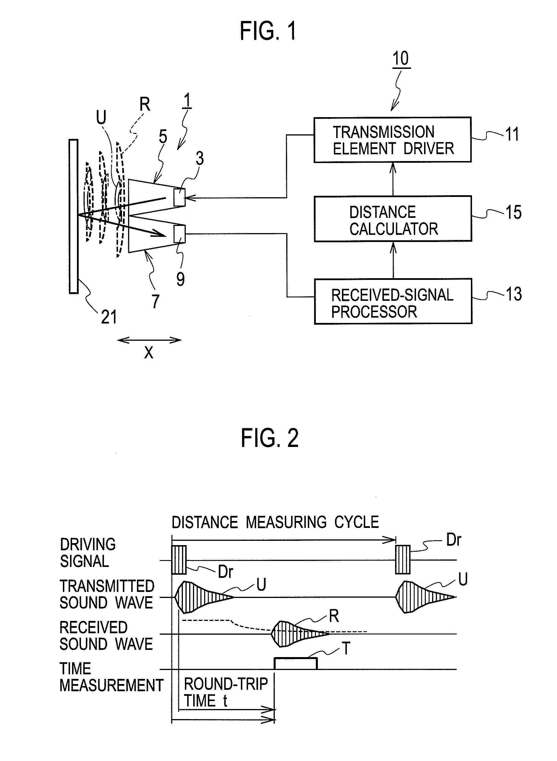
[0024]FIG. 1 is a view showing the schematic configuration of a distance measuring device of an object to be detected using an ultrasonic sensor according to one embodiment of the present invention.

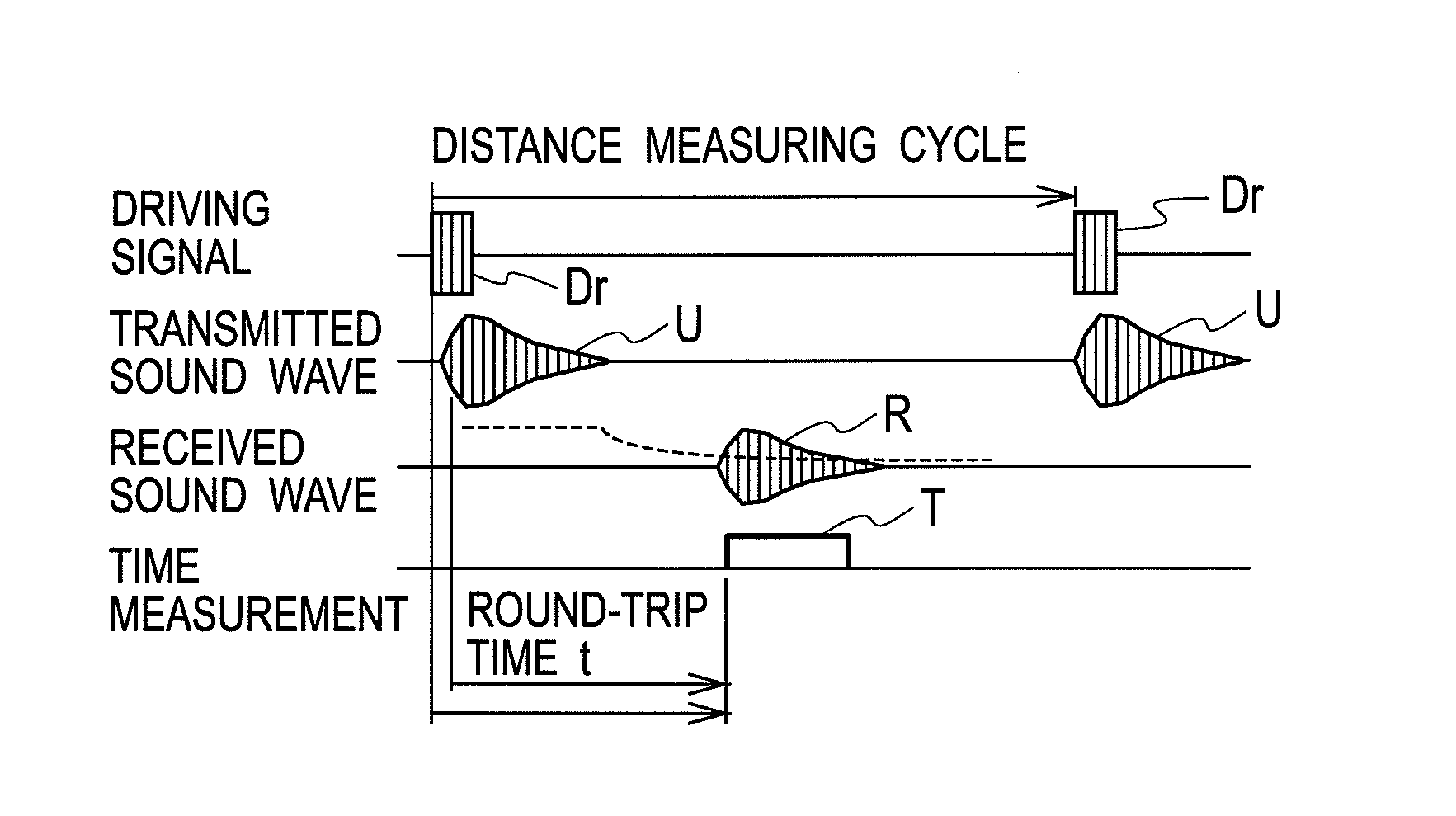
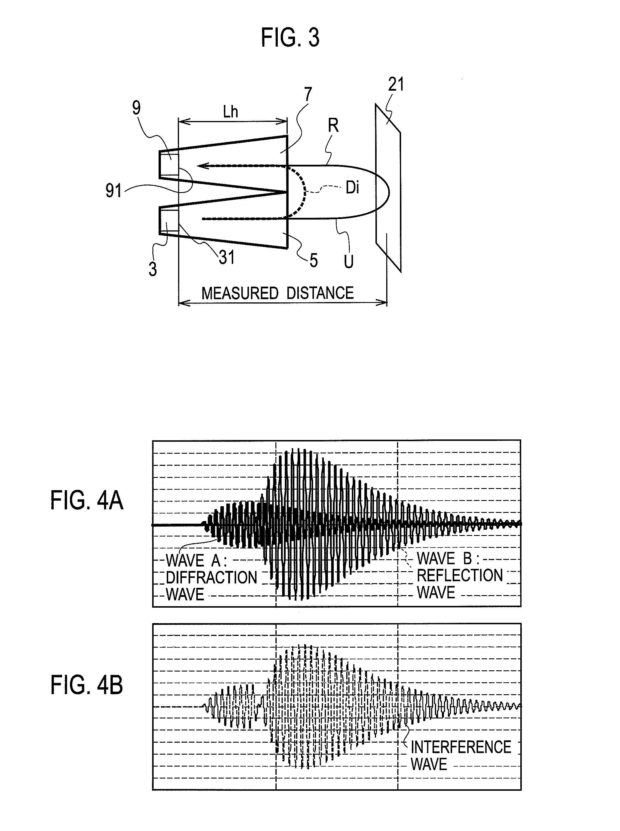
[0025]As shown in FIG. 1, the distance measuring device of the present embodiment includes an ultrasonic sensor 1 and a control unit 10. In the ultrasonic sensor 1, an ultrasonic wave U is emitted toward an object to be detected 21 via a transmitting horn 5 from a transmission element 3 transmitting the ultrasonic wave, and a reflection wave R from the object to be detected 21 is received by a reception element 9 via a receiving horn 7. The control unit 10 includes a transmission element driver 11 driving the transmission element 3, a received-signal processor 13 processing a received signal obtained by the receive element, and a distance calculator 15 controlling the tra...


PUM


Abstract

As a transmitting horn or a receiving horn attached to a transmission element or a reception element of an ultrasonic sensor, a horn enclosure with two acoustic horn bodies having a dimensional difference ΔLh of a quarter λ / 4 of the wavelength λ of an ultrasonic wave U in the propagation direction X of the ultrasonic wave U or a reflection wave R is used. Then, the amplitude of a diffraction wave A1 and the amplitude of a diffraction wave A2 in opposite phase between a transmission side and a reception side are caused to match with each other so as to cancel out both the diffraction waves A1, A2 in a common sound space of the horn enclosure, which is not partitioned for each acoustic horn body by a screen, on a front of the reception element.

Description

BACKGROUND OF THE INVENTION[0001]1. Technical Field[0002]The present invention relates to ultrasonic sensors that measure a distance to an object to be detected and the like by transmitting / receiving an ultrasonic wave.[0003]2. Background Arts[0004]The ultrasonic sensor is widely used for applications, such as in measuring a distance to an object to be detected and in detecting the presence of an object to be detected, as with a photosensor and the like. In particular, the ultrasonic sensor is used for the detection of an object to be detected, which a photosensor is not good at detecting, such as the detection of a transparent or semi-transparent film, such as an ultralight paper or a master for a stencil printing plate, the detection of the position of a paper, both sides of which are printed in black, or the detection of the liquid level of ink or the like, in the field of printing, for example.[0005]In the ultrasonic sensor, an ultrasonic wave is transmitted toward an object to ...

Claims


Application Information

Patent Timeline
IPC IPC(8): G01N29/07
CPCG01S7/521G01S15/10G01C3/06G01N29/07G10K11/00G10K11/18G01N29/14G01N29/24
Inventor SUZUKI, MASAO
Owner RISO KAGAKU CORP
Why Eureka
Try Eureka