Power supply device

a power supply device and power supply technology, applied in the direction of electric variable regulation, process and machine control, instruments, etc., can solve the problems of high cost of communication methods, large system configuration requirements of non-contact or wireless data communication systems, and difficulty in realizing simple and less expensive configurations of non-contact data communication of power supply devices. achieve the effect of high reliability against dust in the environment where the power supply device is used

Inactive Publication Date: 2013-04-25
MINEBEAMITSUMI INC
View PDF5 Cites 5 Cited by
  • Summary
  • Abstract
  • Description
  • Claims
  • Application Information

AI Technical Summary

Benefits of technology

[0015]According to an embodiment of the present invention described above, by removing the sealing material from the opening provided on the enclosure just before using the probe pin of the writer of the control information to be sent to the power supply unit, and the sealing material is put back over the opening, the degree of airtightness is kept high while utilizing the power supply device so that reliability against dust in the environment where the power supply device is used becomes high.

Problems solved by technology

The following problems occur when transmitting the control parameters from the external device to the power supply device.
Further, it is anticipated that the cost of communication method will be an expensive depending on the configuration of the data communication method.
However, the system configurations of these non-contact or wireless data communication system requires relatively large system configuration in general.
Accordingly, it has been difficult to realize a simple and less expensive configuration of a non-contact data communication of the power supply device.

Method used


Image

  • Power supply device
  • Power supply device
  • Power supply device

Examples


Embodiment Construction

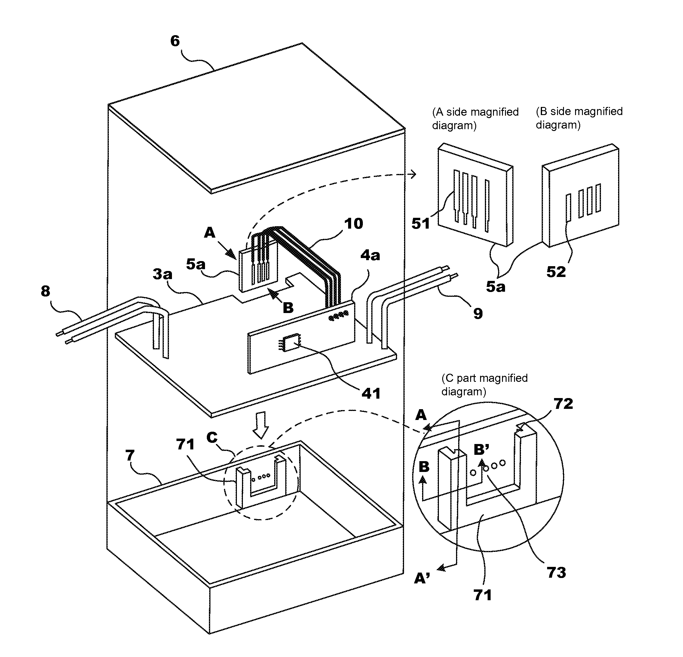
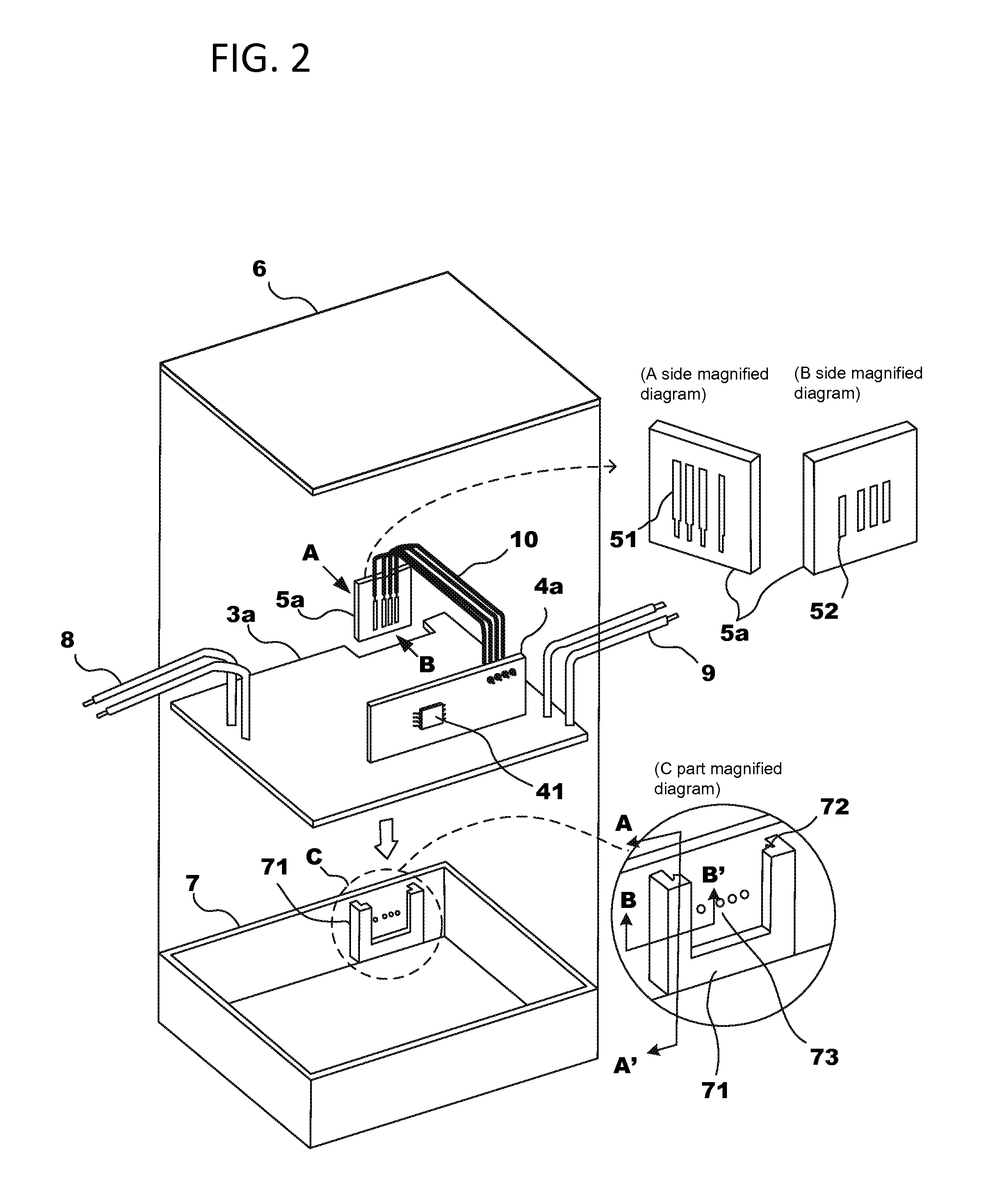
[0026]Referring to the drawings, the following describes the details of the power supply device being an embodiment of the present invention. The scope of the present invention is not limited to those drawings.

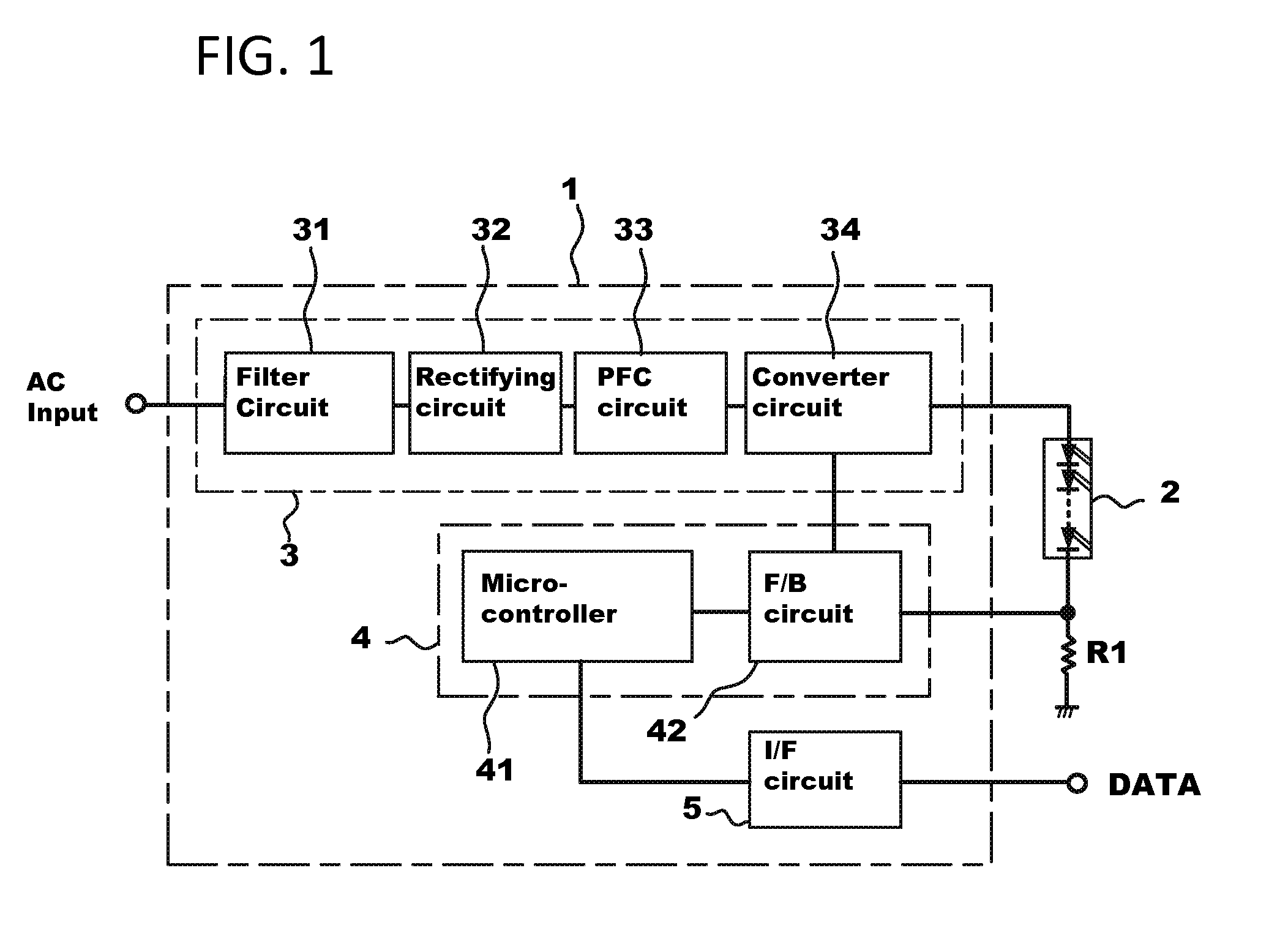
[0027]FIG. 1 illustrates a block diagram which illustrates the basic circuit configuration of a power supply device 1. As illustrated in FIG. 1, the power supply device 1 is comprised of a power supply unit 3, a control circuit unit 4 and an I / F circuit 5. The power supply unit 3 converts inputted alternating-current voltage to direct-current voltage and supplies power to an LED module 2 as a load of the power supply device 1. The control circuit unit 4 controls the operation of the power supply unit 3 and optimizes the output current and / or the output voltage according to the specifications of the LED module 2. The I / F circuit 5 has functions for communicating (sending and / or receiving) control parameters (control information) between an outside device and the power supply de...


PUM


Abstract

A power supply device containing a first board, a second board, an enclosure into which the first board and the second board are installed, a power supply unit which supplies power to an external load, a control circuit unit for controlling output current and/or output voltage from the power supply unit to the external load, the control circuit unit being embedded on the first board, a memory which stores control information, the memory being utilized in the control circuit unit for controlling the output current and/or the output voltage from the power supply unit, and an interface unit which is capable of receiving the control information from an external device and transmitting the control information to the memory, the interface unit being embedded on the second board which is physically separated from the first board.

Description

[0001]This application claims benefit of prior-filed provisional App. No 61 / 550,897 entitled “Power-Supply Apparatus” filed on Oct. 24, 2011 in the name of Shinichi Suzuki, said provisional application being hereby incorporated by reference as if fully set forth herein.[0002]1. Field of the Invention[0003]The field of the present invention relates to power supply devices for supplying power to loads such as LED modules as lighting devices. In particular, described herein is an apparatus and a method for enabling the change of control parameters of the power supply device to optimize the output voltage and / or current to the load such as LED modules from an external device, corresponding to the changes of the specifications of LED modules, such as, power consumptions, input voltage of the LED modules.[0004]2. Background[0005]The product specifications of LED modules are specified by, for example, optical qualities such as visible output colors, number of LEDs, intensity or brightness,...

Claims


Application Information

Patent Timeline
Patent Type & Authority Applications(United States)
IPC IPC(8): H05B37/02G06F1/26H05B44/00
CPCH05B37/0254H05B33/0845H05B33/0815H05B45/10H05B47/18H05B45/37
Inventor SUZUKI, SHINICHISAITO, KAZUAKI
Owner MINEBEAMITSUMI INC
Why Eureka
Try Eureka