
Method and system of automatic control

a technology of automatic control and control method, applied in the direction of position/direction control, weapons, military adjustment, etc., can solve the problems of large resources, ineffective “lowering trail temperature” technique, and inability to guarantee flight safety, so as to reduce the probability of a missile hitting and ensure protection reliability

Inactive Publication Date: 2007-04-26
ZAKRYTOE AKTSIONERNOYE OBSCHESTVO STIVT
View PDF5 Cites 2 Cited by
  • Summary
  • Abstract
  • Description
  • Claims
  • Application Information

AI Technical Summary

Benefits of technology

[0013] Therefore, the object of the claimed invention is to reduce a probability of a missile hit to a civil aircraft and to ensure protection reliability in optical interference environment.

Problems solved by technology

However, this technique required great resources and could not guarantee the flight safety because of great area of “risk zone” (zone from which there is a possibility to hit a flying aircraft).
The “lowering trail temperature” technique is not effective.
But even such lowering is very ineffective protection means from modern missiles that find their targets in the case of low temperature of engine.
The “strengthening aircraft” technique is restricted in practice use.
An exact place of missile hit into an aircraft is unpredictable.
Weight and cost of modernization being expected in the case of mounting armour onto a whole aircraft are ultimately high.
But when mounting armour only onto critical aircraft assemblies (such as engines, fuel tanks, cockpit, and electronics units), the most part of aircraft will remain still vulnerable for a missile.
It should be noted that such targets are expensive and danger.
However, pyrotechnic targets could provoke a fire, if they fall down onto the earth prior to be burned out completely.
The purpose of such actions is often to wreck the process of guiding an infrared seeker head to an aircraft.
Thus, the problem of protecting civil aircrafts from the aforementioned arm is of extreme actuality at the present.

Method used


Image

  • Method and system of automatic control
  • Method and system of automatic control
  • Method and system of automatic control

Examples


Embodiment Construction

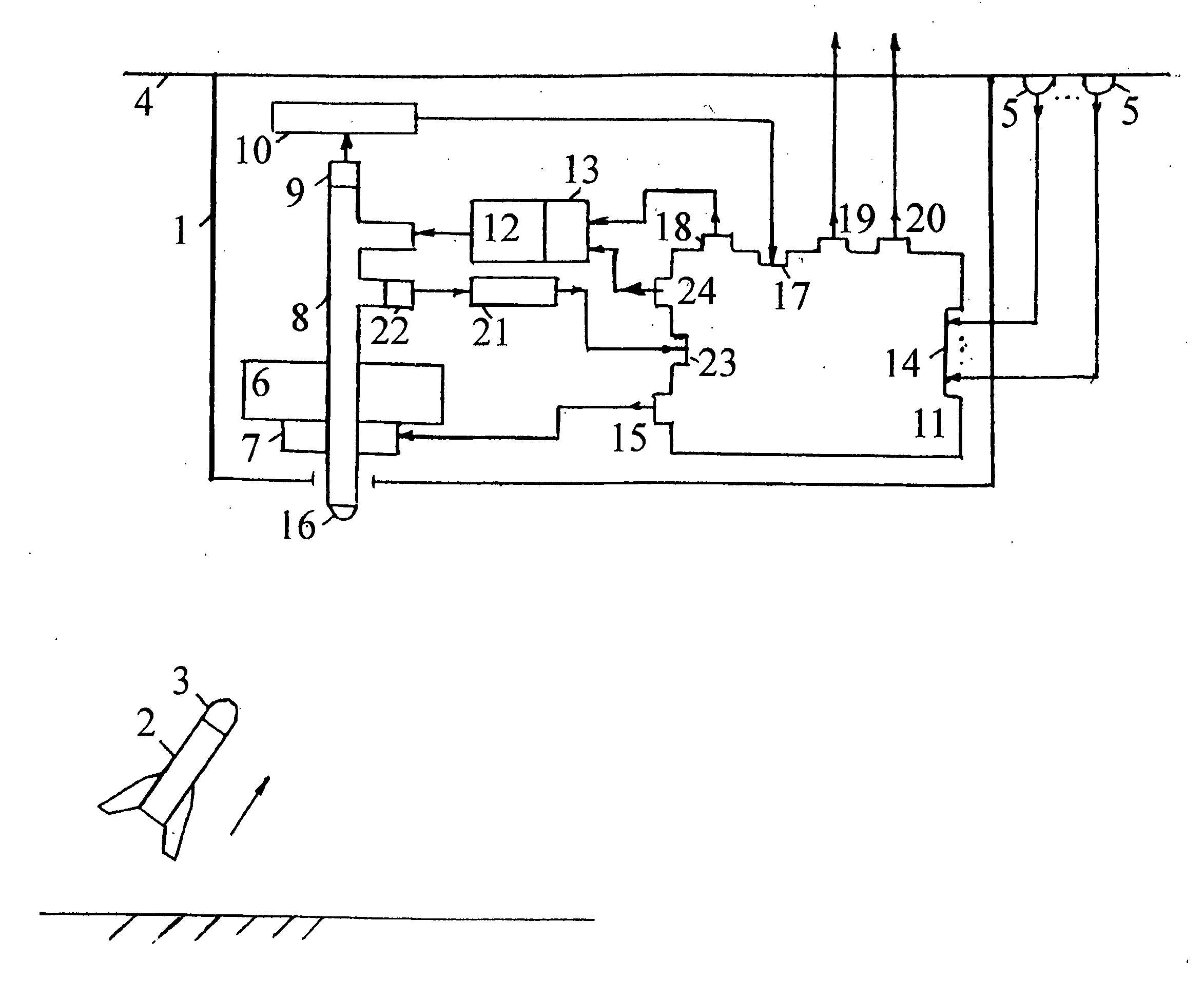
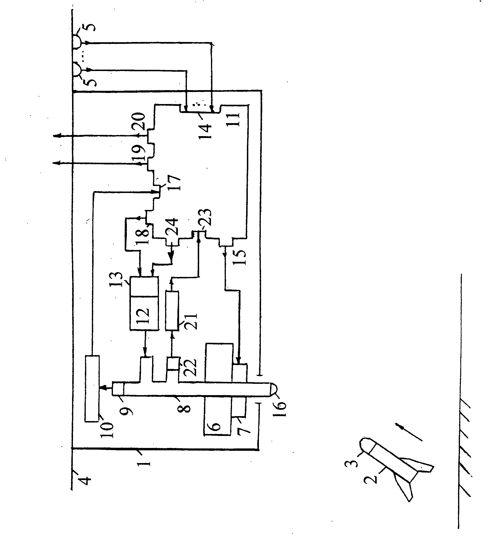
[0024] The drawing shows schematically a situation of protecting a civil aircraft from missiles with seeker heads of portable anti-aircraft missile complexes and a structure of system for protecting a civil aircraft from missiles with seeker heads of portable anti-aircraft missile complexes.

[0025] The system 1 for protecting a civil aircraft (see the drawing) from missiles 2 with seeker heads of portable anti-aircraft missile complexes comprises, on board the civil aircraft 4 being protected: sensors 5 of the fact and coordinates of missile launch; a transceiver 6 having a turn drive 7 and an optical channel 8 which output 9 is connected to a sensor 10 of missile coordinates at a missile flight trajectory; an on-board calculator 11; and a laser radiation generator 12 having an actuation device 13. The first group inputs 14 of the on-board calculator 11 are connected to the outputs of sensors 5 of the fact and coordinates of missile launch in order to calculate the coordinates of mi...


PUM


Abstract

The invention relates to aircraft automatic control systems. Its use for providing flight safety of civil aircrafts allows to obtain the technical result in the form of reducing a probability of a missile hit on a civil aircraft and ensuring protection reliability in optical interference environment. This technical result is achieved in the method due to steps of: determining the fact of a missile launch; determining missile coordinates in every time moment; generating pulse periodic laser radiation, wherein a wavelength range of the laser radiation is within a sensitivity range of infrared seeker head, a power of the laser radiation exceeds the power of radiation of the aircraft engine in the sensitivity range of the infrared seeker head, and a pulse repetition frequency is close to typical operation frequency of the infrared seeker head; and sending the laser radiation to the point of presence of the missile in the given time moment. This result is ensured in the system by arranging at an aircraft and employing sensors of missile launch fact and coordinates, a transceiver having a turn drive and an optical channel which output is connected to a sensor of missile coordinates at a missile flight trajectory, an on-board calculator, and a laser radiation generator having an actuation device.

Description

FIELD OF THE INVENTION [0001] This invention relates to aircraft automatic control systems. The field of employment of present inventions is to provide flight safety of civil aircrafts. BACKGROUND OF THE INVENTION [0002] In practice, various techniques are employed in order to solve the problem for providing flight safety of civil aircrafts from missile attacks: [0003] 1. The “elimination of missile launch place”, where a locality is guarded and patrolled. However, this technique required great resources and could not guarantee the flight safety because of great area of “risk zone” (zone from which there is a possibility to hit a flying aircraft). [0004] 2. The “lowering trail temperature” technique is not effective. Missiles having infrared (IR) seeker heads react to heat energy and are guided to a jet aircraft because of high temperature of its engine and exhaust gases. It is possible to decrease a little an IR heat trail by means of pumping air additionally around an engine exhau...

Claims


Application Information

Patent Timeline
Patent Type & Authority Applications(United States)
IPC IPC(8): B64D7/00G05D1/00F41H11/00G01S7/495
CPCF41H11/02F41H13/0056G01S7/495
Inventor KISLETSOV, ALEXANDER VASILYEVICHSYGUROV, PETER NIKOLAEVICHBUTUZOV, VLADIMIR VASILYEVICHVELIKANOV, SERGEY DMITRIEVICH
Owner ZAKRYTOE AKTSIONERNOYE OBSCHESTVO STIVT
Learn More