Brushless motor control method, brushless motor control device and electric power steering apparatus

a technology of motor control and control device, which is applied in the direction of electric generator control, dynamo-electric converter control, dynamo-electric gear control, etc., can solve the problems of large load placed on computing elements, computation is possible, and computation is extremely large, so as to reduce the load on the cpu at the time of motor control, the effect of reducing the torque rippl

Inactive Publication Date: 2013-04-25
MITSUBA CORP
View PDF5 Cites 33 Cited by
  • Summary
  • Abstract
  • Description
  • Claims
  • Application Information

AI Technical Summary

Benefits of technology

[0011]It is an object of the present invention to provide a motor control method and a motor control device, which are capable of reducing a torque ripple of a brushless motor without placing a large computation load on a CPU.
[0013]According to the present invention, current-correction values, which can diminish the torque ripple for the magnet torque and the torque ripple for the reluctance torque, are set by using a preset correction map while the maximum-torque control is performed. In the correction map, the relationships between the phase-current values and correction parameters are stored. The CPU refers to the correction map based on the detected current value to determine the parameters. In this manner, it is no longer necessary for the CPU to constantly calculate the torque ripple and sequentially compute the command value for diminishing the torque ripple. Thus, in the brushless motor, the load on the CPU at the time of motor control is significantly reduced while the torque ripple is suppressed. As a result, the torque ripple of the brushless motor can be reduced without using a high-performance CPU, and hence system cost can be reduced.
[0017]According to the present invention, the first harmonic component which can diminish the torque ripple for the magnet torque and the second harmonic component which can diminish the torque ripple for the reluctance torque are calculated by using the preset correction map by the correction-component calculating section, while the fundamental-wave currents at the time of the maximum-torque control are calculated by the fundamental-current calculating section. In the correction map, the relationships between the phase-current values and the correction parameters are stored. The correction-component calculating section refers to the correction map based on the detected current value to determine the parameters so as to calculate the first harmonic component and the second harmonic component. The current-correcting section corrects the fundamental-wave currents based on the first harmonic component and the second harmonic component. As a result, the control device is no longer required to constantly calculate the torque ripple and sequentially compute the command value for diminishing the torque ripple. Thus, in the brushless motor, the load on the CPU at the time of motor control is significantly reduced while the torque ripple is suppressed.
[0020]According to the present invention, in the electric power steering apparatus, the current-correction values, which can diminish the torque ripple for the magnet torque and the torque ripple for the reluctance torque, are set by using the preset correction map while the maximum-torque control is performed. In the correction map, the relationships between the phase-current values and the correction parameters are stored. The CPU refers to the correction map based on the detected current value to determine the parameters. In this manner, it is no longer necessary for the CPU to constantly calculate the torque ripple and sequentially compute the command value for diminishing the torque ripple. Thus, in the brushless motor, the load on the CPU at the time of motor control is significantly reduced while the torque ripple is suppressed. Moreover, the torque ripple is reduced to a predetermined value or smaller (for example, 5% or smaller) to improve a steering feeling. As a result, the steering feeling can be improved without using a high-performance CPU. Thus, the system cost of the EPS can be reduced.

Problems solved by technology

However, a computation load is extremely large.
Therefore, a large load is placed on a computing element.
Such computation is possible in theory but is difficult in practice.

Method used


Image

  • Brushless motor control method, brushless motor control device and electric power steering apparatus
  • Brushless motor control method, brushless motor control device and electric power steering apparatus
  • Brushless motor control method, brushless motor control device and electric power steering apparatus

Examples


first embodiment

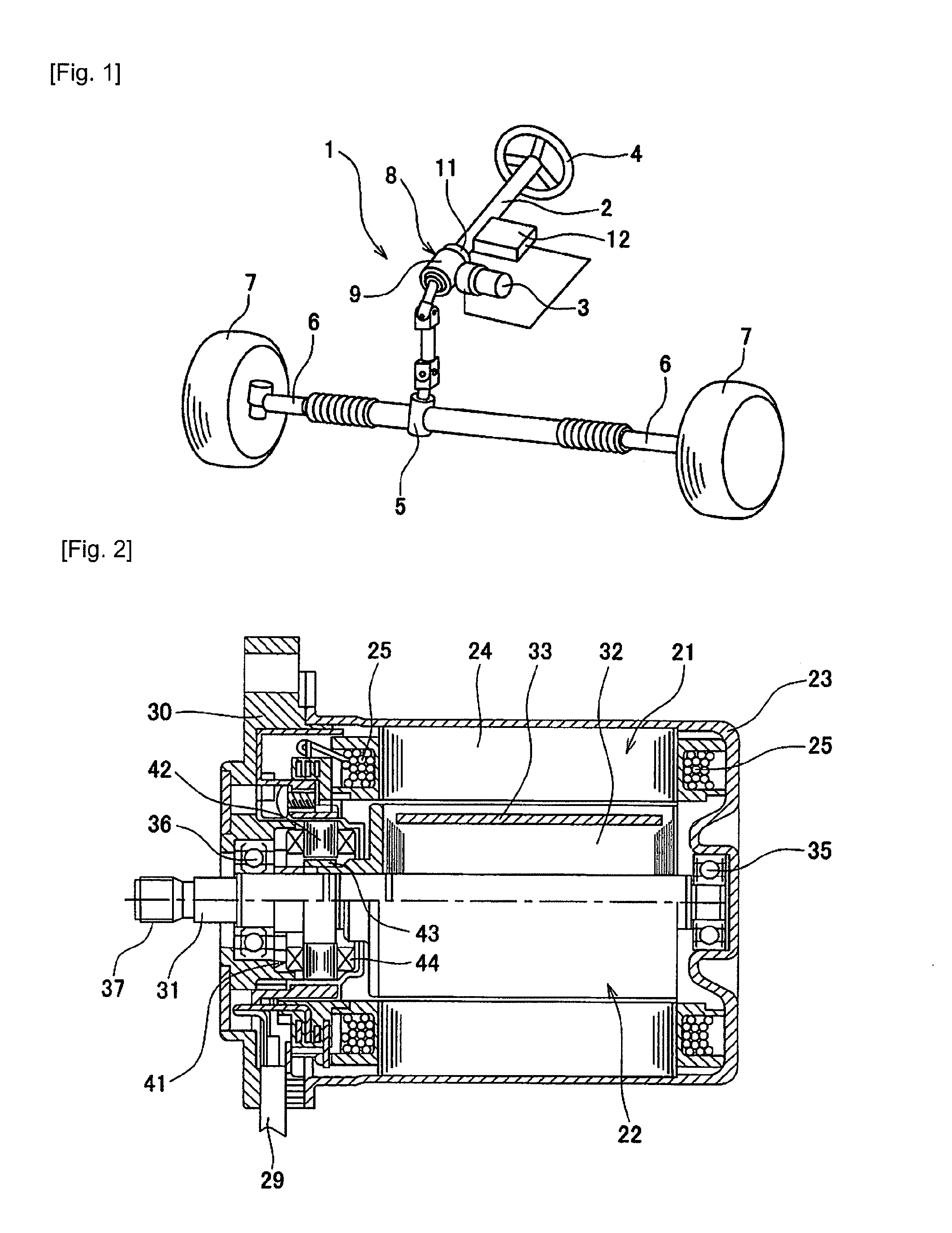
[0035]FIG. 1 is an explanatory view illustrating a configuration of an EPS using a brushless motor. Control processing according to the present invention is performed in the EPS illustrated in FIG. 1. An electric power steering apparatus (EPS) 1 illustrated in FIG. 1 is a column-assist type device for applying an operation assist force to a steering shaft 2. In the EPS 1, a brushless motor 3 (hereinafter abbreviated as “motor 3”) is used as a power source.

[0036]A steering wheel 4 is mounted to the steering shaft 2. A steering force to the steering wheel 4 is transmitted to a tie rod 6 through a pinion and a rack shaft (both not shown) provided in a steering gear box 5. Wheels 7 are respectively connected to both ends of the tie rod 6. The tie rod 6 is actuated along with an operation of the steering wheel 4 to horizontally steer the wheels 7 through knuckle arms (not shown) or the like.

[0037]In the EPS 1, an assist motor section 8, which is a steering-force assist mechanism, is prov...

second embodiment

[0068]Next, as a second embodiment of the present invention, the case where the present invention is applied to a brushless motor having a 10-pole 12-slot (10P12S) configuration is described. In the following embodiment, the same members and portions as those of the first embodiment are denoted by the same reference symbols, and the description thereof is herein omitted.

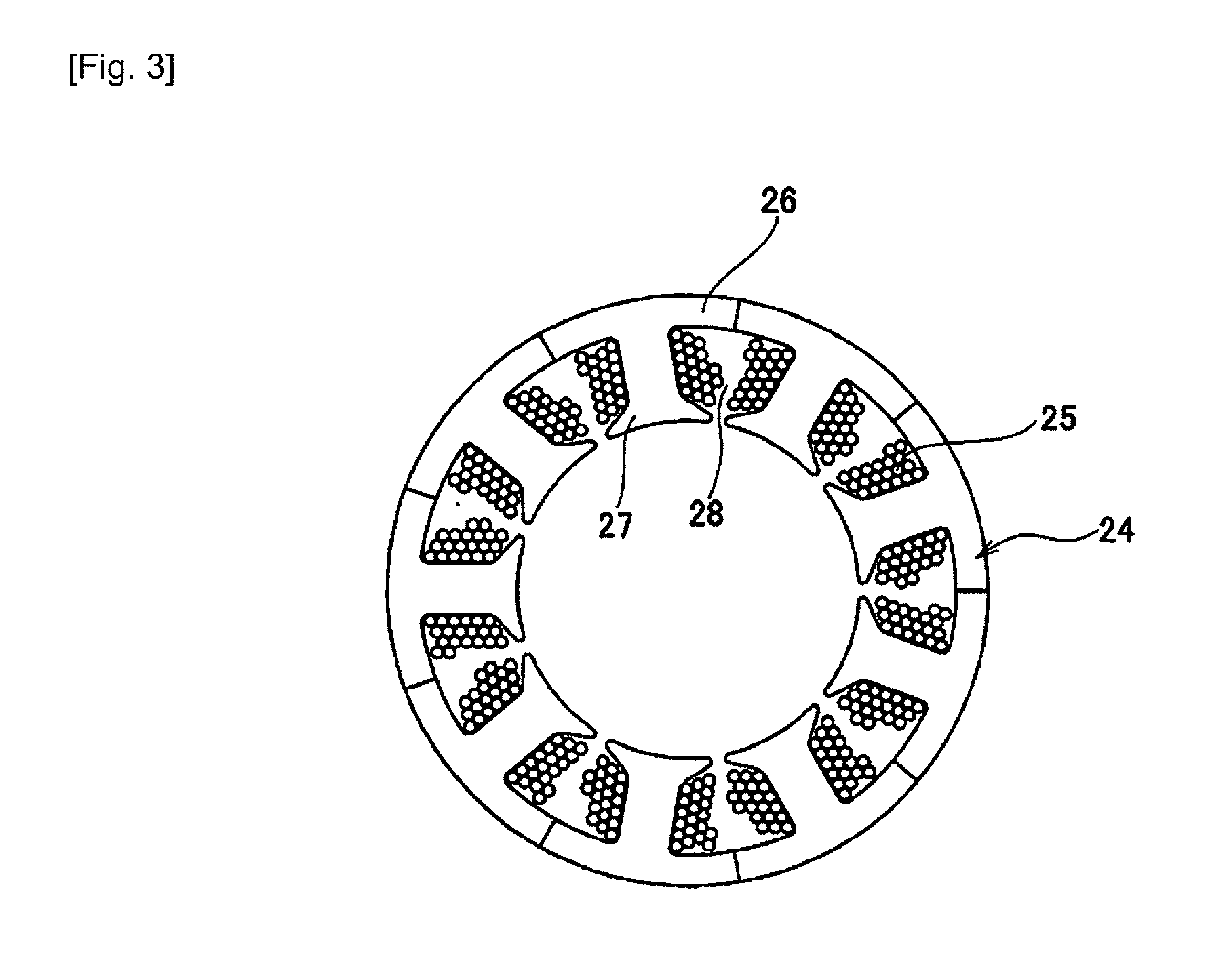
[0069]FIG. 11 is an explanatory view illustrating a configuration of a brushless motor 71 (hereinafter abbreviated as “motor 71”). A stator core 72 of the brushless motor 71 similarly includes the ring-shaped yoke portion 26 and the teeth 27 formed so as to project in the inward direction from the yoke portion 26. The number of provided teeth 27 is twelve. The slots 28 (twelve in number) are formed between the teeth 27. On the inner side of the stator core 72, the rotor 22 is provided. Similarly to the motor 3 of the first embodiment, the magnets 33 are embedded in the rotor core 32 (IPM-motor structure). Ten magnets...


PUM


Abstract

A control device (50) for an IPM-type brushless motor (3) includes a fundamental-current calculating section (52) for calculating fundamental-wave currents indicating winding current values to be set in maximum-torque control, a correction-component calculating section (59) for calculating a first harmonic component (B sin 6(θ+β)) for cancelling a torque ripple for a magnet torque and a second harmonic component (A sin 6(θ+α)) for cancelling a torque ripple for a reluctance torque based on phase-current values detected by a current sensor (64), a correction map (58) storing relationships between the phase currents and parameters (A, B, α, and β) of the first harmonic component and the second harmonic component, and a current-correcting section (60) for superimposing the first harmonic component and the second harmonic component respectively on the fundamental-wave currents to correct a current to be supplied so as to generate current command values (Id′ and Iq′).

Description

BACKGROUND OF THE INVENTION[0001]1. Field of the Invention[0002]The present invention relates to a technology for reducing a torque ripple in a brushless motor, and more particularly, to a technology which is effective when being applied to a brushless motor to be used as a driving source of an electric power steering apparatus.[0003]2. Related Art Statement[0004]In recent years, the use of a so-called interior permanent magnet (IPM) type motor (hereinafter abbreviated as “IPM motor”) in which a permanent magnet is embedded in a rotor has increased as a driving source for an electric power steering apparatus (hereinafter abbreviated as “EPS”). In the IPM motor, the magnet is embedded in the rotor. Therefore, a difference in inductance between a d-axis (central axis of the permanent magnet) direction and a q-axis (axis electrically and magnetically orthogonal to the d-axis) direction is large. As a result, a reluctance torque Tr is generated in the rotor. Therefore, in the case of th...

Claims


Application Information

Patent Timeline
Patent Type & Authority Applications(United States)
IPC IPC(8): H02P6/10H02P6/06H02P6/08H02P6/28H02P21/00H02P21/05H02P21/22H02P23/04H02P27/04
CPCB62D5/046H02P6/10
Inventor OKUBO, MASAYUKI
Owner MITSUBA CORP
Why Eureka
Try Eureka