Current sensor

a current sensor and sensor technology, applied in the field of current sensors, can solve the problems of reducing the symmetry property of the positional relationship between the plural magnetic sensors with respect, insufficient gap used for providing the cutout portion leading the current line onto the substrate, and insufficient gap, etc., to achieve the effect of reducing the increase in manufacturing cost or enhancing the measurement accuracy, and suppressing the increase in the size of the current sensor

Inactive Publication Date: 2013-04-25
ALPS ALPINE CO LTD
View PDF7 Cites 26 Cited by
  • Summary
  • Abstract
  • Description
  • Claims
  • Application Information

AI Technical Summary

Benefits of technology

[0016]In the current sensor according to preferred embodiments of the present invention, it is desirable that the first magnetic detector element group includes four magnetic detector elements provided so as to face each other with being mutually located at equal distances from the current line, and the second magnetic detector element group includes four magnetic detector elements provided so as to face each other with being mutually located at equal distances from the current line. According to this configuration, since the total number of magnetic detector elements becomes eight, it may be possible to desirably suppress an increase in a manufacturing cost or an increase in the size of the current sensor, associated with an increase in the number of the magnetic detector elements, while it may be possible to reduce a measurement error when the current line is displaced and it may be possible to desirably enhance the measurement accuracy.
[0017]In the current sensor according to preferred embodiments of the present invention, it is desirable that the first and second supporting surfaces form circumferential surfaces following an outer peripheral surface of the current line and when the current line is attached, the first and second supports are fixed so that the first and second cutout portions are out of phase with each other by at least 90 degrees in the circumferential direction of the current line. According to this configuration, since the first and second supporting surfaces forming circumferential surfaces following an outer peripheral surface of the current line support the current line from directions out of phase with each other by at least 90 degrees, a range surrounded by the first or second supporting surface becomes narrower than a square shape circumscribed by a circle whose radius is equal to a circular arc formed by the supporting surfaces. Accordingly, it may be possible to fix the current line with accuracy, and it may be possible to further improve the measurement accuracy of the current sensor.
[0018]It is desirable that the current sensor according to preferred embodiments of the present invention further includes a third support configured to include a third cutout portion leading the current line conducting therethrough the current to be measured and a third supporting surface being provided in the third cutout portion and supporting the current line led from the third cutout portion, and a third magnetic detector element group configured to be provided in the third support and include a plurality of magnetic detector elements outputting output signals owing to the induction magnetic field, wherein the first, second, and third supports lead the

Problems solved by technology

However, in the current sensor described in Japanese Unexamined Patent Application Publication No. 2007-107972, when a large number of magnetic sensors are provided that are used for enhancing the measurement accuracy and the detection sensitivity of the current to be measured, a gap used for providing a cutout portion leading the current line onto a substrate becomes insufficient.
Therefore, there occurs a problem that it is difficult to

Method used


Image

  • Current sensor
  • Current sensor
  • Current sensor

Examples


first embodiment

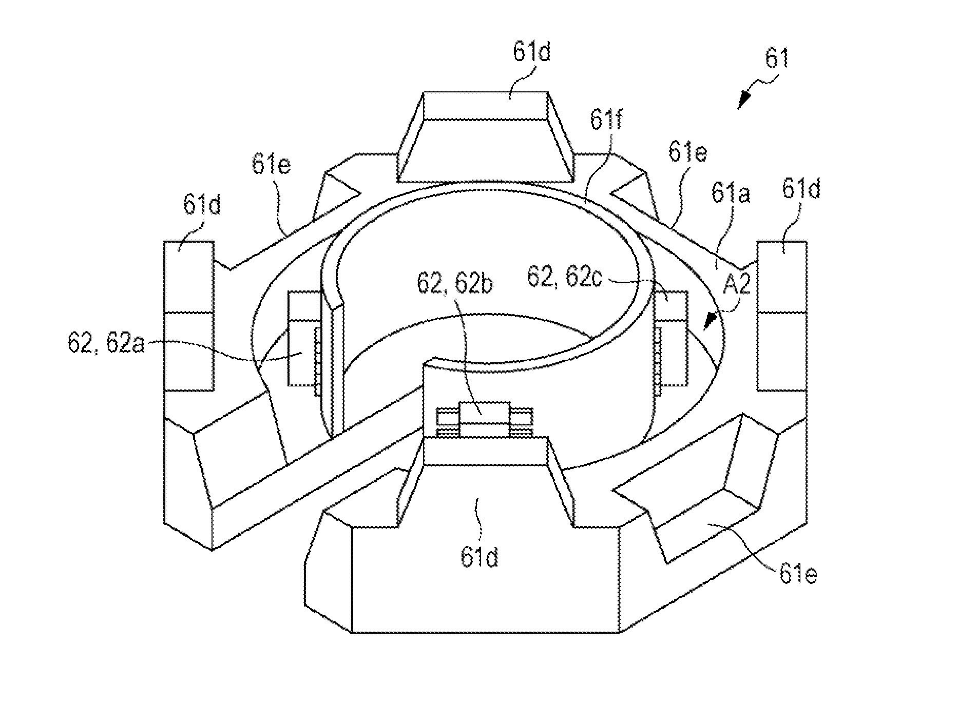
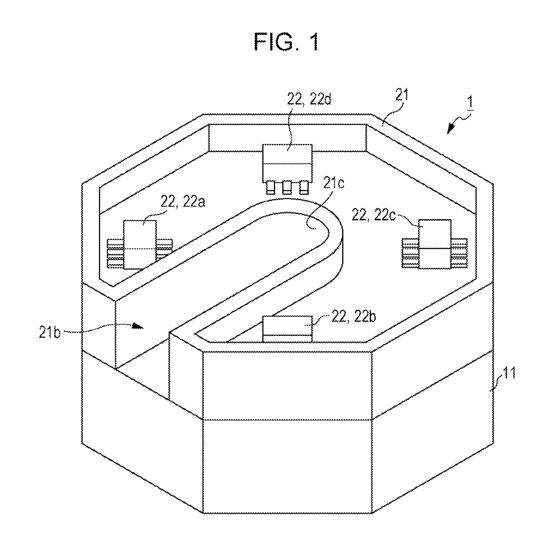
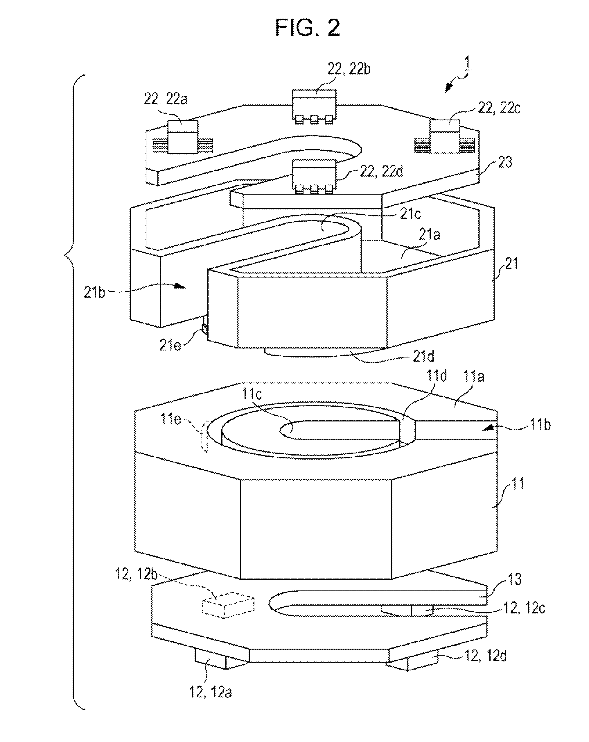
[0043]FIG. 1 is the external appearance perspective view of a current sensor according to a first embodiment. FIG. 2 is the exploded perspective view of the current sensor according to the present embodiment. In addition, for convenience of explanation, it is assumed that each of front-back, vertical, and horizontal directions is in accordance with a direction illustrated in FIG. 1.

[0044]As illustrated in FIG. 1 and FIG. 2, a current sensor 1 according to the present embodiment includes a first support 11, a second support 21 fixed on the first support 11 so as to be rotatable in a horizontal direction (the circumferential direction of a current line X: refer to FIGS. 5A and 5B), a first magnetic detector element group 12 including a plurality of magnetic detector elements that are provided on the first support 11 and output output signals owing to an induction magnetic field from a current to be measured, and a second magnetic detector element group 22 including a plurality of magn...

second embodiment

[0081]Next, a second embodiment of the present invention will be described. In a current sensor 2 according to the present embodiment, a plurality of magnetic detector element groups are provided in a concentric fashion with respect to a current line, and the individual magnetic detector element groups are mutually provided on substantially the same circumference of circle (within substantially the same plane). In addition, hereinafter, differences from the current sensor 1 according to the first embodiment will be mainly described and the duplication of description will be avoided.

[0082]FIG. 9 is the external appearance perspective view of the current sensor 2 according to the second embodiment of the present invention, and FIG. 10 is the exploded perspective view of the current sensor 2 according to the present embodiment.

[0083]As illustrated in FIG. 9 and FIG. 10, the current sensor 2 includes a pair of first and second supports 31 and 41 that have a same configuration and are co...


PUM


Abstract

A current sensor includes a first support configured to include a cutout portion, a first magnetic detector element group configured to be provided in the first support, a second support configured to include a cutout portion, and a second magnetic detector element group configured to be provided in the second support. The cutout portion includes a supporting surface supporting a current line. In the current sensor, when the current line conducting therethrough a current to be measured is attached, the first support and the second support are displaced in the circumferential direction of the current line and fixed, and the current line is supported by supporting surfaces, in different positions in the axis line direction of the corresponding current line.

Description

CLAIM OF PRIORITY[0001]This application claims benefit of Japanese Patent Application No. 2011-230783 filed on Oct. 20, 2011, which is hereby incorporated by reference.BACKGROUND OF THE INVENTION[0002]1. Field of the Invention[0003]The present invention relates to a current sensor for measuring a current to be measured that is conducted through a current line, and relates to, for example, a current sensor equipped with a magnetic detector element.[0004]2. Description of the Related Art[0005]In the field of technologies for driving motors in electric vehicles, hybrid vehicles, and the like, since relatively large currents are handled, a current sensor is desirable that is capable of contactlessly measuring a large current. As such a current sensor, a current sensor has been proposed that detects a change in a magnetic field occurring owing to a current to be measured, using a plurality of magnetic sensors.[0006]The current sensor includes a substrate, in which a cutout is provided so...

Claims


Application Information

Patent Timeline
IPC IPC(8): G01R19/00
CPCG01R15/207
Inventor MITSUYA, SHINJI
Owner ALPS ALPINE CO LTD
Why Eureka
Try Eureka