Optical system and image pickup apparatus

a technology of optical system and image pickup, which is applied in the field of optical system, can solve the problems of difficult to obtain desired optical performance, and increasing the variation of various aberrations with respect to manufacturing errors, so as to achieve the effect of easy manufacturing

Inactive Publication Date: 2013-04-25
CANON KK
View PDF5 Cites 9 Cited by
  • Summary
  • Abstract
  • Description
  • Claims
  • Application Information

AI Technical Summary

Benefits of technology

[0009]The present invention provides an optical system and an image pic...

Problems solved by technology

When the refractive power of each unit is simply strengthened in order to reduce the size of the front lens unit, an amount of variation of various aberrations is increased with respect to various kinds of manufacturing errors.
In this case, the manufacture is difficult since surface accuracy or assembly accuracy that is required for each lens unit (especially the front lens unit), and as a result, it is difficult to obtain a desired optical performance.
However, in the configuration of the front...

Method used


Image

  • Optical system and image pickup apparatus
  • Optical system and image pickup apparatus
  • Optical system and image pickup apparatus

Examples


embodiment 1

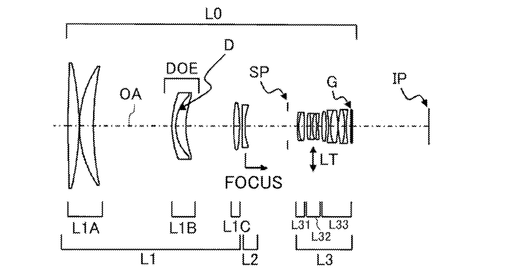
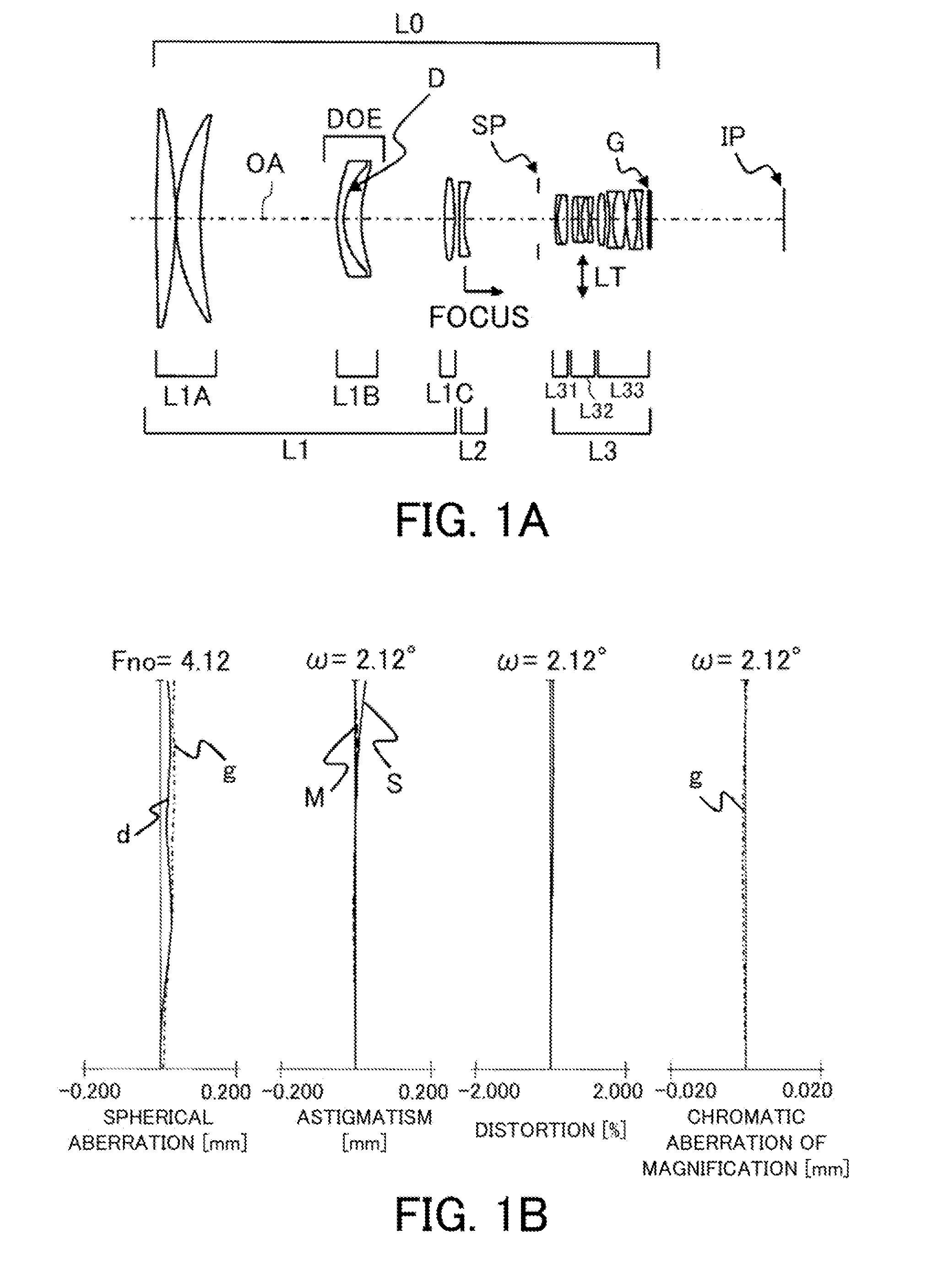
[0097]First of all, referring to FIG. 1A, the image pickup optical system L0 (the optical system) in Embodiment 1 of the present invention will be described. The first lens unit L1 is, in order from the object side to the image side, configured by the first partial lens unit L1A, the second partial lens unit L1B, and the third partial lens unit L1C. Each of the two positive lens components in the first partial lens unit L1A is a single lens that has a positive refractive power, and in order from the object side to the image side, they are configured by a biconvex lens and a meniscus lens having a convex shape at the object side. The second partial lens unit L1B includes one cemented lens, and this cemented lens is, in order from the object side to the image side, configured by cementation of a meniscus lens having a negative refractive power and having a convex shape at the object side and a meniscus lens having a positive power and having a convex shape at the object side. This cem...

embodiment 2

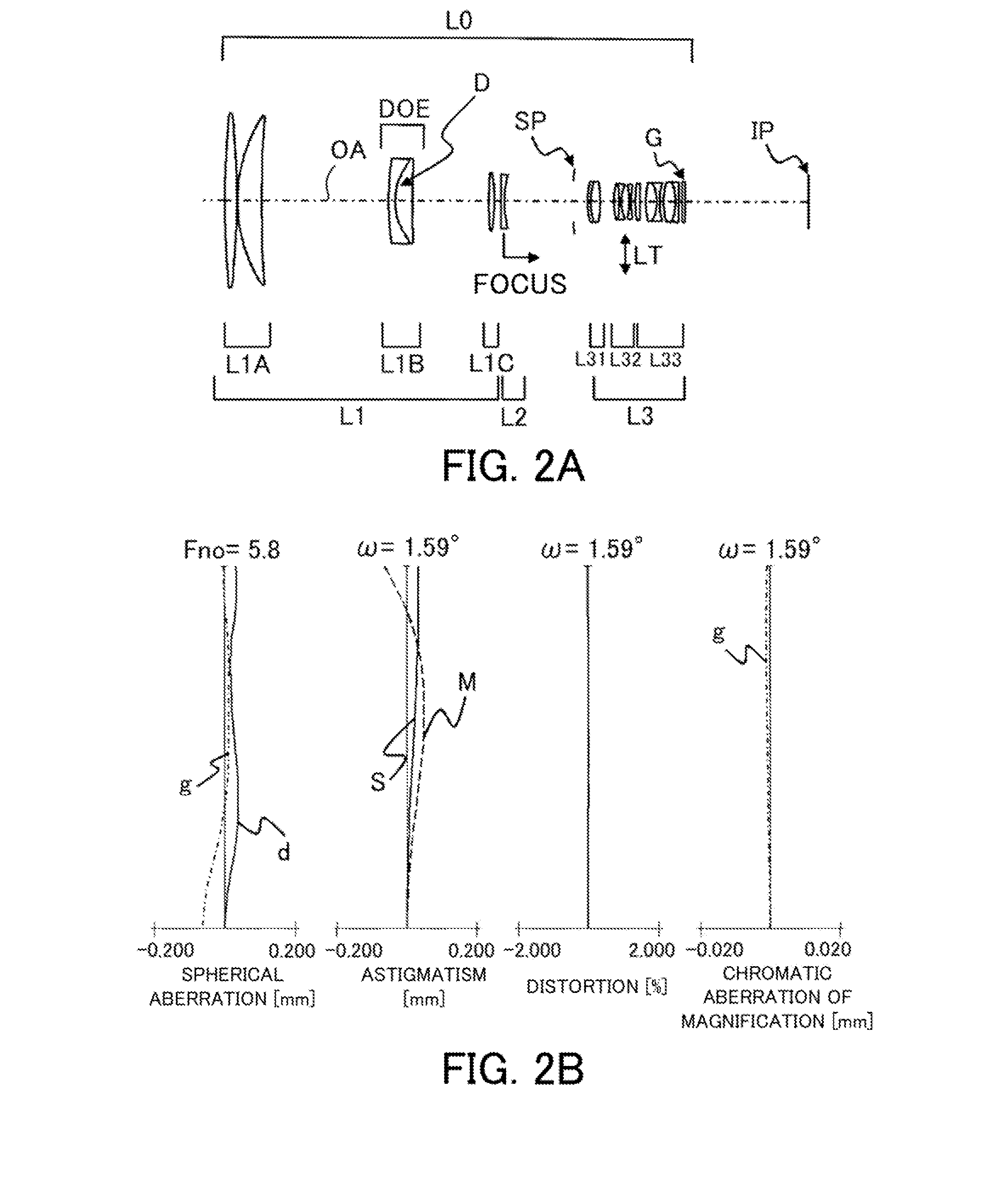
[0099]Next, referring to FIG. 2A, the image pickup optical system L0 (the optical system) in Embodiment 2 of the present invention will be described. The first lens unit L1 is, in order from the object side to the image side, configured by the first partial lens unit L1A, the second partial lens unit L1B, and the third partial lens unit L1C. Each of the two positive lens components in the first partial lens unit L1A has a single lens having a positive refractive power, and the two positive lens is, in order from the object side to the image side, configured by a biconvex lens and a meniscus lens having a biconvex shape at the object side. The second partial lens unit L1B is configured by one cemented lens, and this cemented lens is, in order from the object side to the image side, configured by cementation of a meniscus lens having a negative refractive power and having a convex shape at the object side and a meniscus lens having a positive refractive power and having a convex shape...

embodiment 3

[0101]Next, referring to FIG. 3A, the image pickup optical system L0 (the optical system) in Embodiment 3 of the present invention will be described. The first lens unit L1 is, in order from the object side to the image side, configured by the first partial lens unit L1A, the second partial lens unit L1B, and the third partial lens unit L1C. Each of the two positive lens components in the first partial lens unit L1A has a single lens having a positive refractive power, and the two positive lens is, in order from the object side to the image side, configured by a biconvex lens and a meniscus lens having a biconvex shape at the object side. The second partial lens unit L1B is configured by one cemented lens. This cemented lens is, in order from the object side to the image side, configured by cementation of a meniscus lens having a negative refractive power and having a convex shape at the object side and a meniscus lens having a positive refractive power and having a convex shape at ...


PUM


Abstract

An optical system includes a first lens unit fixed during a focusing operation and having a positive refractive power, a second lens unit moving in an optical axis direction during the focusing operation and having a negative refractive power, a third lens unit positioned at the image side relative to the second lens unit and having a positive or negative refractive power, the first lens unit is configured by first, second, and third partial lens units, the first partial lens unit is configured by two positive lens components, the second partial lens unit is configured by one cemented lens having a negative combined refractive power, the third partial lens unit is positioned between the second partial lens unit and the second lens unit and has a positive refractive power as a whole, and each lens unit is configured so as to meet an appropriate condition.

Description

BACKGROUND OF THE INVENTION[0001]1. Field of the Invention[0002]The present invention relates to an optical system that is suitably used for an image pickup apparatus such as a digital still camera or a video camera using a solid-state image pickup element or a camera using a silver salt film.[0003]2. Description of the Related Art[0004]As an image pickup optical system of a long focal length, a so-called telephoto-type image pickup optical system (a telephoto lens) that is, in order from an object side to an image side, configured by a front lens unit having a positive refractive power and a rear lens unit having a negative refractive power is known. The long focal length, for example, means a focal length that is longer than a size of an effective image pickup range. Commonly, in the telephoto lens having a long focal length, a total lens length becomes long as the foal length is extended. When a telephoto lens which has a small F-number (an aperture ratio) is obtained, especially...

Claims


Application Information

Patent Timeline
IPC IPC(8): G03B13/00G02B9/12
CPCG02B27/4211G02B13/02
Inventor EGUCHI, KAORU
Owner CANON KK
Why Eureka
Try Eureka