Apparatus and Method for Transporting Substrates

a technology for transporting substrates and apparatuses, applied in the direction of liquid surface applicators, coatings, railway bodies, etc., can solve the problem that substrates cannot be moved at the same speed, and achieve the effect of reducing the number of printing heads or processing stations in the device for the printing process

Inactive Publication Date: 2013-04-25
SCHMID TECH
View PDF0 Cites 2 Cited by
  • Summary
  • Abstract
  • Description
  • Claims
  • Application Information

AI Technical Summary

Benefits of technology

[0012]A further aspect of the invention concerns a device for printing or coating a substrate, said device comprising or using an apparatus as described above. A substrate can then be introduced into the device using this apparatus. The device has a first processing station, at which a substrate transported thereto is measured, in particular in terms of its relative position to the holding means and/or to the traversing device and thus also to the device itself. A second processing station then follows, in which the substrate is then printed or coated, wherein a plurality of processing stations may also be provided for this purpose. In this second

Problems solved by technology

However, a disadvantage is that the subst

Method used


Image

  • Apparatus and Method for Transporting Substrates
  • Apparatus and Method for Transporting Substrates
  • Apparatus and Method for Transporting Substrates

Examples


Embodiment Construction

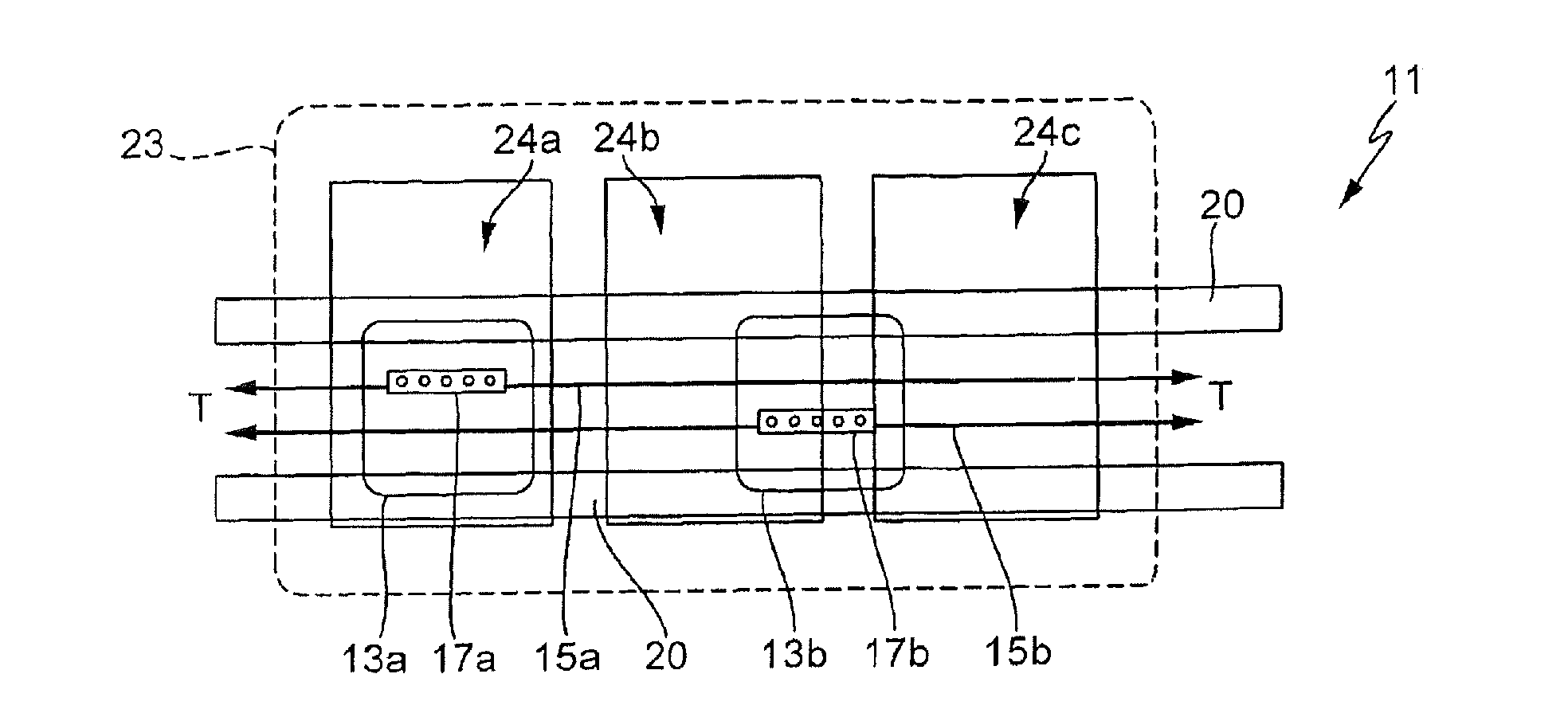
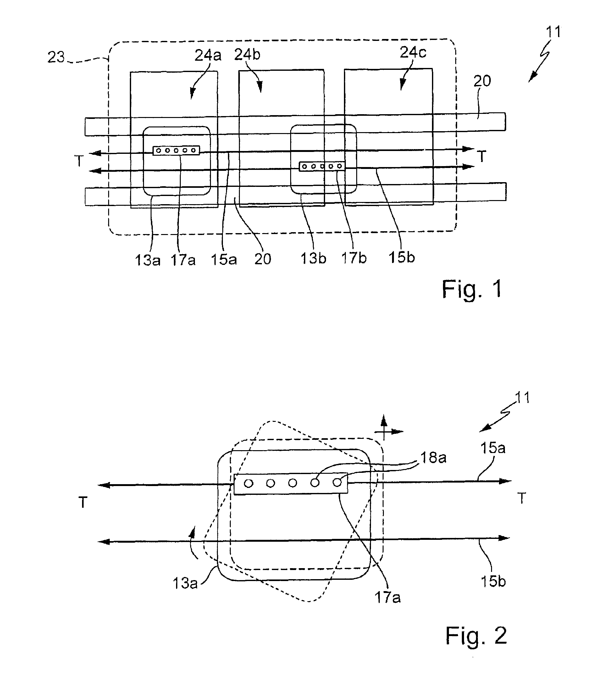
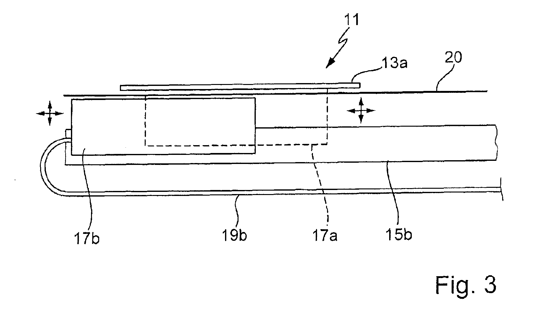
[0018]FIG. 1 shows a plan view of a transporting apparatus 11 according to the invention, with which wafers 13a and 13b as flat substrates can be transported or moved along a direction of transport T in a plane of transport, which is advantageously horizontal. The transporting apparatus 11 has two transporting rails 15a and 15b along the direction of transport T, on which transporting carriages 17a and 17b are provided. A single transporting carriage 17 is advantageously, but not necessarily, provided per transporting rail 15. The arrangement of the transporting carriage on the transporting rail 15 can also be seen from FIG. 3 for example and is explained in greater detail in this regard with reference to FIG. 3. Reference is made to the possible aforementioned embodiments, which are known in principle to a person skilled in the art. A transporting carriage 17 may overlap the transporting rail 15 in a virtually U-shaped manner, if said transporting rail is a single rail. Alternative...


PUM


Abstract

An apparatus for transporting silicon wafers in a horizontal transporting direction into a printing device has two transporting units, which each have a traversing device and a holding means thereon. At least two transporting units each with a holding means are provided, wherein the traversing devices of said units run next to each other along the transporting direction. The holding means are each formed and arranged in such a way that an unloaded holding means has space to pass by a holding means loaded with a silicon wafer. The traversing devices are rails and the holding means are carriages mounted thereon.

Description

FIELD OF APPLICATION AND PRIOR ART[0001]The invention relates to an apparatus for transporting substrates, such as flat silicon wafers, along a direction of transport, and to a corresponding method, and to a device which uses such an apparatus.[0002]Substrates such as silicon wafers are normally transported between different processing stations on a roller conveyor or conveying belts, more specifically in succession. In some circumstances, a plurality of roller conveyors or a plurality of rows of substrates can be provided side by side. This is known from DE 102006054846 A1 for example. However, a disadvantage is that the substrates can only be moved at the same speed. If, therefore, one substrate requires slightly more processing time or one processing station requires more time than a previous or subsequent processing station, this results in delays, which should actually be avoided in the expensive installations used.[0003]Furthermore, it is known for example from DE 102005039100...

Claims


Application Information

Patent Timeline
IPC IPC(8): B05C13/02
CPCH01L21/67748H01L21/67784B05C13/02H01L21/68764H01L21/68714
Inventor SOLLNER, JURGENSAUTER, THOMASMUNKEL, JENSBUCHNER, CHRISTIAN
Owner SCHMID TECH
Why Eureka
Try Eureka