Pleurodesis catheter with coated and shielded tip

Inactive Publication Date: 2013-04-25
CAREFUSION 2200 INC
View PDF9 Cites 11 Cited by
  • Summary
  • Abstract
  • Description
  • Claims
  • Application Information

AI Technical Summary

Benefits of technology

This patent describes catheter devices that can develop a sclerotic agent from a coated surface while keeping the device away from direct tissue contact. The catheter can have mechanical barriers or other structures to prevent tissue from touching the device surface, rely on fluid diffusion from a protected sclerotic agent coating, or use other methods to achieve the desired effect. The technical effect is to minimize tissue damage and improve the efficacy and safety of catheter treatment procedures.

Problems solved by technology

A disruption in the balance between the movement of fluid into the pleural space and the movement of fluid out of the pleural space may produce excessive fluid accumulation in the pleural space.
The clinical manifestations of pleural effusion include dyspnea, cough and chest pain which diminish the patient's quality of life.
Such patients may develop progressive pleural effusions that eventually do produce symptoms requiring treatment, but some will reach a stage where the effusions and reabsorption reach an equilibrium that is still asymptomatic and does not necessitate treatment.
However, pleurectomy is a major surgical procedure associated with substantial morbidity and some mortality.
In general, systemic chemotherapy is disappointing for the control of malignant pleural effusions.
Such procedures are painful to the patient, both initially when the chest tube is inserted and during the time it remains within the pleural space.
There are a number of difficulties in thoracentesis, including the risk of puncturing a lung with the catheter tip or with the needle used to introduce the catheter, the risk of collapsing a lung by relieving the negative pressure in the pleural space, the possibility of aggravating the pleural effusion by stimulating fluid production in the introduction of the catheter, and the risk of infection.
One of the primary difficulties with ordinary thoracentesis procedures is that fluid reaccumulates in the pleural space relatively quickly after the procedure is performed, and so it is necessary to perform the procedure repeatedly—as often as every few days.
Chemical pleurodesis may be a painful procedure, so patients are often premedicated with a sedative and analgesics.

Method used


Image

  • Pleurodesis catheter with coated and shielded tip
  • Pleurodesis catheter with coated and shielded tip
  • Pleurodesis catheter with coated and shielded tip

Examples


Embodiment Construction

[0021]Embodiments generally are described with reference to the drawings in which like elements are generally referred to by like numerals. The relationship and functioning of the various elements of the embodiments may better be understood by reference to the following detailed description. However, embodiments are not limited to those illustrated in the drawings. It should be understood that the drawings are not necessarily to scale, and in certain instances details may have been omitted that are not necessary for an understanding of embodiments of the present invention, such as—for example—conventional fabrication and assembly.

[0022]The present invention now will be described more fully hereinafter. This invention may, however, be embodied in many different forms and should not be construed as limited to the embodiments set forth herein; rather, these embodiments are provided so that this disclosure will be thorough and complete, and will fully convey the scope of the invention t...


PUM


Abstract

System and components for inducing pleurodesis while minimizing likelihood of tissue damage from direct application of pleurodesis-enhancing materials. A tube device is provided that is configured to elute pleurodesis-enhancing material. The device includes one or more features configured to prevent or lessen the likelihood that the pleurodesis-enhancing material comes into direct and concentrated contact with patient tissue when a distal length of the device is disposed indwelling a patient.

Description

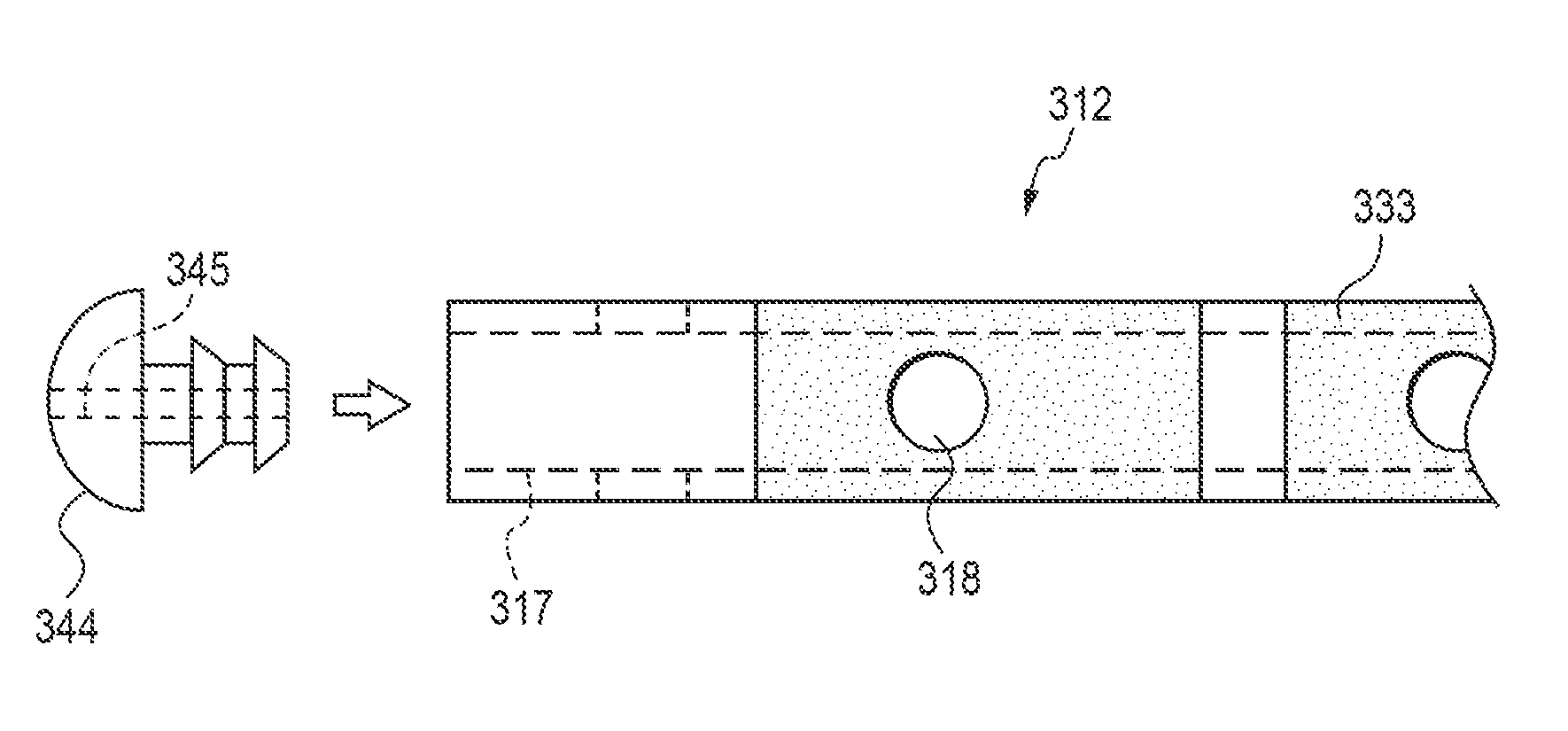
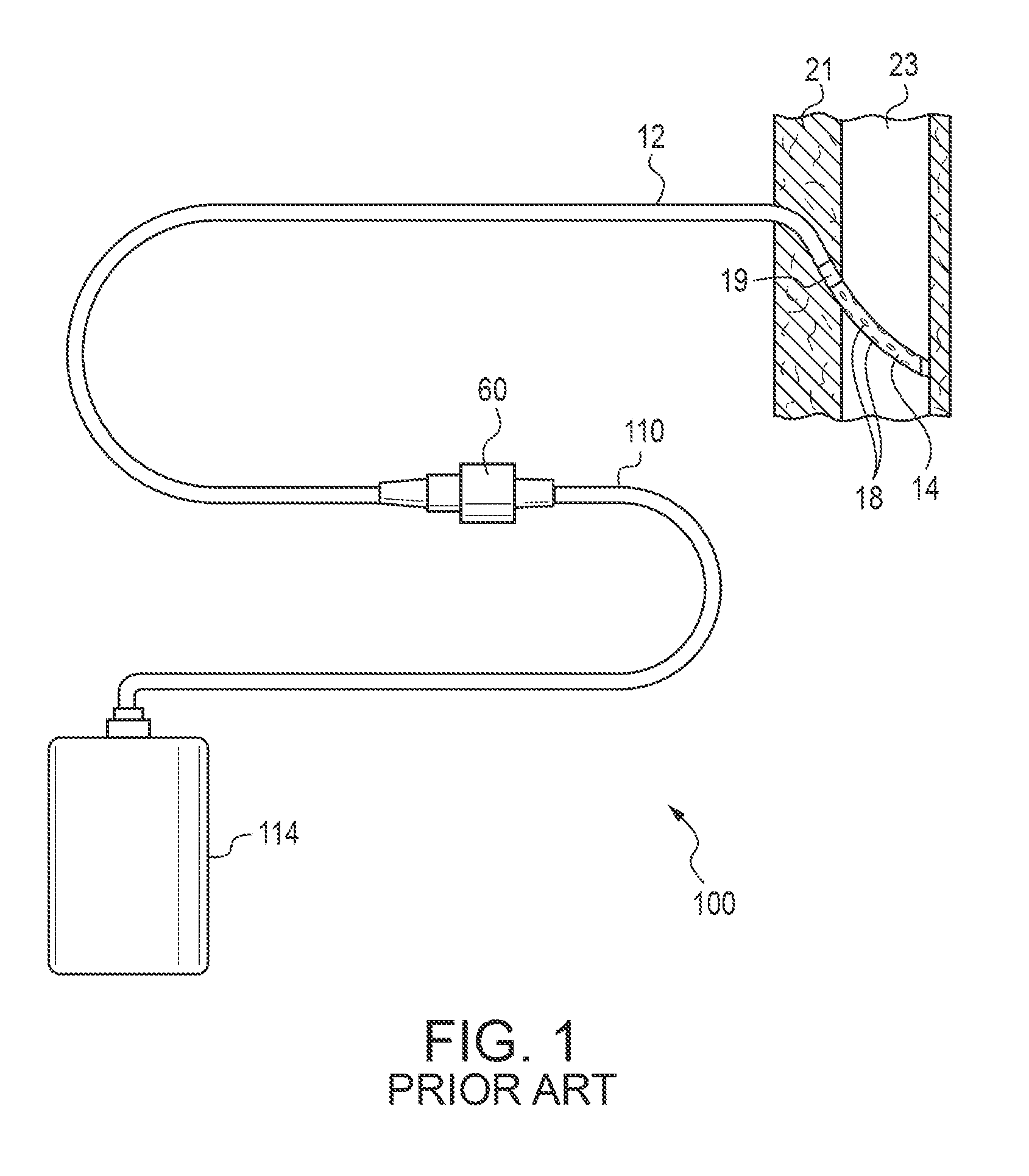
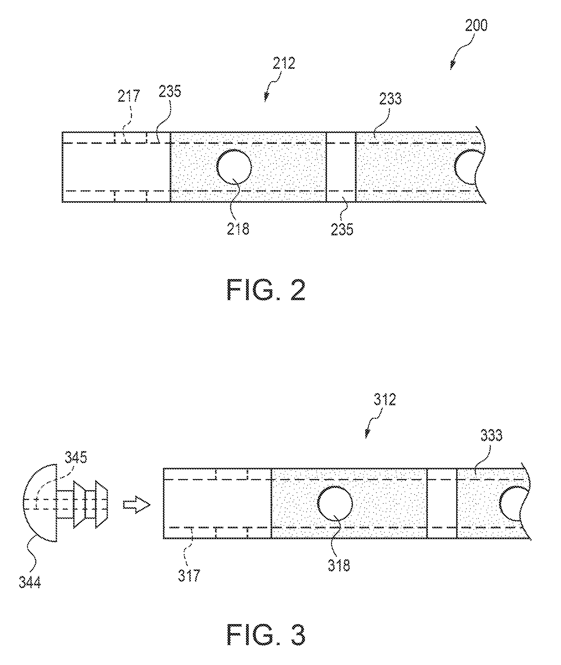
TECHNICAL FIELD[0001]Embodiments of the present invention relate to the field of removing peritoneal ascites, pleural effusion fluids, and the like. More particularly, embodiments of the present invention relate to a catheter device that can perform a drainage function and a sclerosis-inducting function while protecting tissue from direct exposure to concentrated sclerotic agents.BACKGROUND[0002]Ascites describes an accumulation of fluid in the peritoneal cavity. Pleural effusion refers to the effusion of fluid into the pleural space. Both excess fluid accumulation conditions may be treated with a drainage apparatus of the type shown in FIG. 1. The apparatus 100 is shown as installed in a patient body and includes a drainage container 114. The drainage container 114 is removably attached by a proximal tube 110 at a valve 60 to a distal catheter 12. The valve 60 may be configured in any number of ways known in the art for attaching catheters together in a fluid-patent manner, (which ...

Claims


Application Information

Patent Timeline
IPC IPC(8): A61L29/16B05D1/32B05D7/00A61M25/01B05D5/00
CPCA61M25/0009A61M25/0068A61M2025/006A61M2025/0057A61M2025/0018A61M31/00
Inventor LOOPER, ANTHONY M.LANDSMAN, KELLYKRUEGER, JOHN A.
Owner CAREFUSION 2200 INC
Why Eureka
Try Eureka