Arthroscope guide

a technology of arthroscope and guide, which is applied in the field of arthroscopic instruments and implants, can solve the problems of difficult to precisely position the distal end of the arthroscope, and achieve the effect of improving the positioning of screws

Inactive Publication Date: 2013-04-25
ARTHREX MEDIZINISCHE INSTR
View PDF5 Cites 49 Cited by
  • Summary
  • Abstract
  • Description
  • Claims
  • Application Information

AI Technical Summary

Benefits of technology

[0008]The embodiments are based on the object of providing means for improving positioning of screws within a bone plate under the surrounding tissue.

Problems solved by technology

Without such a guide, it is extremely difficult to precisely position the distal end of the arthroscope for viewing a specific section of the surface of the plate with a hole and the screw penetrating the tissue and entering the hole.

Method used


Image

  • Arthroscope guide
  • Arthroscope guide
  • Arthroscope guide

Examples


Embodiment Construction

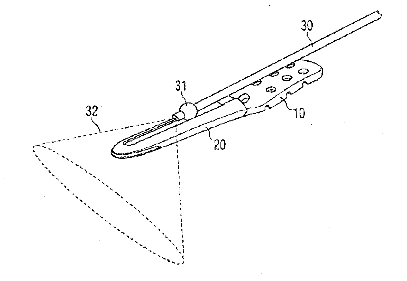
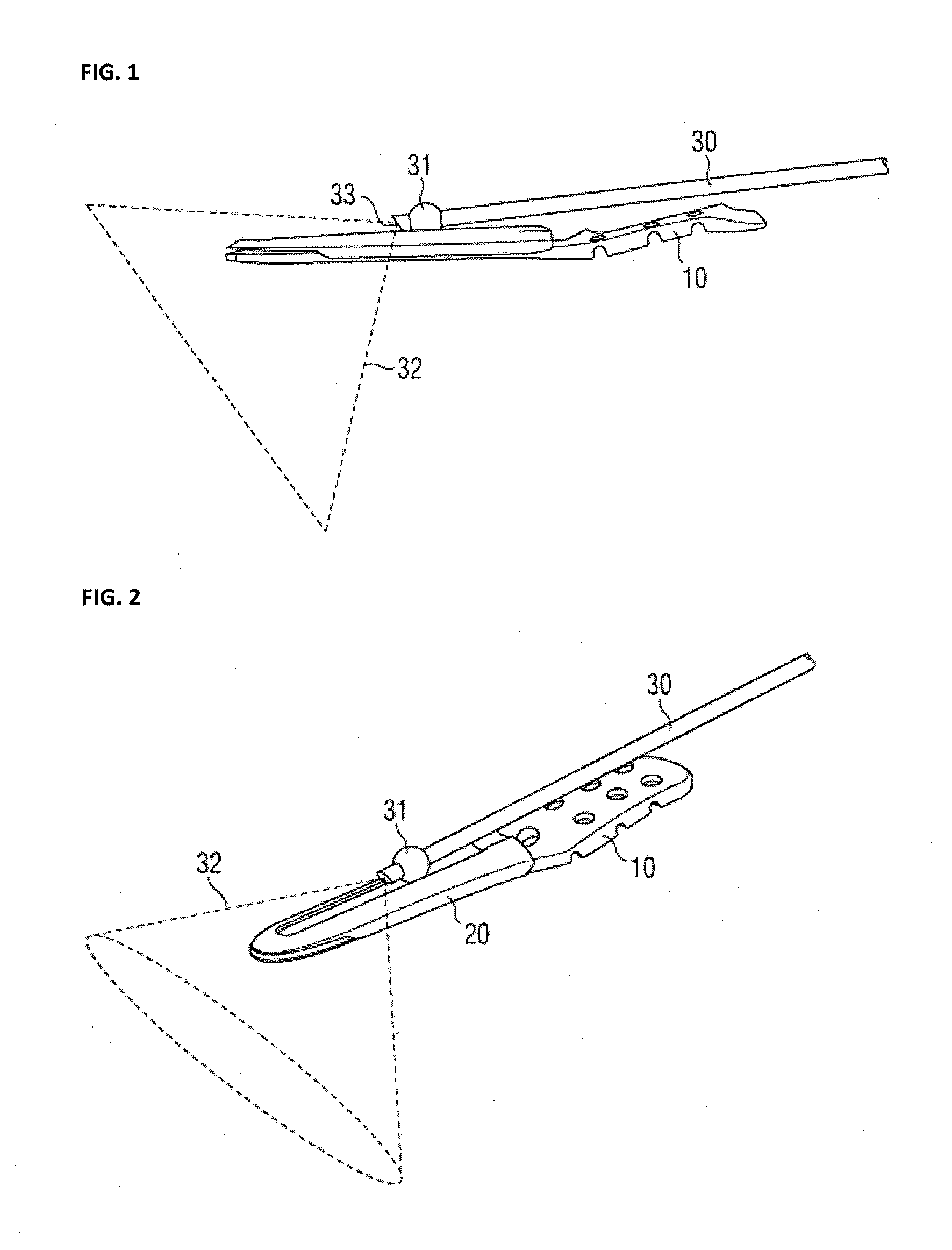
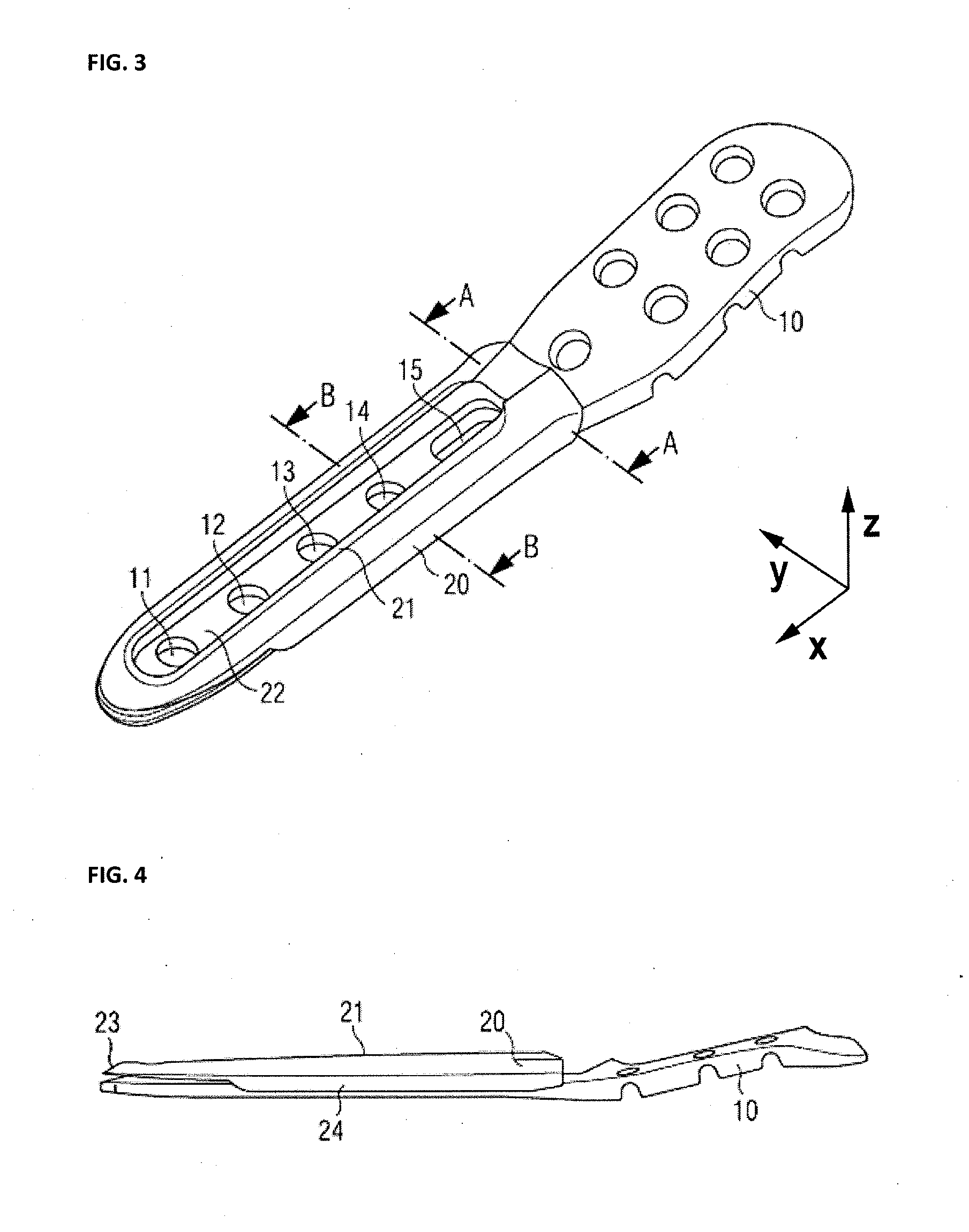
[0026]FIG. 1 shows an embodiment of a slider and a guide. Attached to a bone plate 10 is a guide 20. Both, the bone plate and the guide are inserted into the space between the bone, not shown here and surrounding tissue like muscle, also not shown here. According to the orientation of this figure, the bone would be below the plate, while the tissue would be above the plate and the guide. Furthermore, an arthroscope 30 is inserted into the space between the bone and surrounding tissue, above the plate. Due to the tissue surrounding the bone, the arthroscope may only be inserted roughly parallel to the plate. This arthroscope allows an orthopedic surgeon to locate individual holes in the bone plate and to position screws precisely to hold the bone plate to the bone. The arthroscope is guided by the guide above the surface of the bone plate. This prevents the arthroscope slipping away from the bone plate and the surgeon from losing view of the holes and the screws. The guide preferably...


PUM


Abstract

A guide for guiding the distal end of an arthroscope above the surface of a bone plate is disclosed. The guide is located on top of the bone plate. It has a body with cutouts and/or grooves to guide the arthroscope. Furthermore the arthroscope has a ball shaped slider close to its distal end. This slider is adapted to interface with the guide and allows movement of the distal end of the arthroscope along the cutouts or grooves.

Description

PRIORITY CLAIM[0001]This application claims priority to pending European Patent Application No. 11 182 182.3 filed on Sep. 21, 2011.BACKGROUND OF THE INVENTION[0002]1. Field of the Invention[0003]The present invention relates to arthroscopic instruments and implants, specifically to arthroscopes and implant plates.[0004]2. Description of Relevant Art[0005]For fixing fractures of bones or fixing and stabilizing bones after an osteotomy, bone plates are used. The classic way to apply such a plate is completely opening the operating field. This allows free access to the bone and the plate, so the plate and the screws for fixing the plate can be located precisely. The disadvantages are risk of infection, injury of nerves and vessels and large scars. Therefore, it is preferred to insert the plate through a small incision and push it between the bone and the surrounding tissue. The screws are placed through individual small incisions through the tissue. The drawback of this technique is t...

Claims


Application Information

Patent Timeline
Patent Type & Authority Applications(United States)
IPC IPC(8): A61B17/80
CPCA61B17/808A61B1/0008A61B19/5212A61B1/317A61B17/80A61B1/00154A61B90/361
Inventor KRUPP, STEFANBODINGER, BENEDIKT
Owner ARTHREX MEDIZINISCHE INSTR
Why Eureka
Try Eureka