Artificial blood vessel

a blood vessel and artificial technology, applied in blood vessels, medical science, other medical devices, etc., can solve the problems of vasoconstriction and aneurysm formation, and achieve the effect of preventing the closure of the artificial blood vessel trunk, and preventing the closure of the artificial blood vessel

Inactive Publication Date: 2013-04-25
NIKKISO COMPANY
View PDF8 Cites 33 Cited by
  • Summary
  • Abstract
  • Description
  • Claims
  • Application Information

AI Technical Summary

Benefits of technology

[0007]An advantage of the present invention is provision of an artificial blood vessel which can resist a lateral force.
[0008]According to one aspect of the present invention, there is provided an artificial blood vessel comprising a tubular reinforcement member integrated with a blood vessel wall, wherein the reinforcement member has rigidity to prevent closure of the artificial blood vessel when a lateral force is applied.
[0009]According to another aspect of the present invention, preferably, the artificial blood vessel comprises a trunk portion which forms apart of the blood vessel, and a branch portion branched from the trunk portion. An access port, into which a needle for extracting a fluid from the body or introducing the fluid into the body is inserted, is placed on the branch portion. The tubular reinforcement member integrated with the blood vessel wall of the trunk portion is placed at a position of the trunk portion where the branch portion branches and an adjacent portion thereof. The reinforcement member prevents closure of the artificial blood vessel when a lateral force is applied.
[0010]According to another aspect of the present invention, preferably, in the artificial blood vessel, a blood vessel wall on a portion where the reinforcement member is placed has two layers including an inner wall and an outer wall, the reinforcement member is sandwiched between the inner wall and the outer wall, and the reinforcement member is not exposed to the outside.
[0011]According to another aspect of the present invention, preferably, in the artificial blood vessel, a tubular wall of the reinforcement member has a mesh shape. According to another aspect of the present invention, preferably, in the artificial blood vessel, an opening is formed in the reinforcement member at a position where the branch portion branches, and the trunk portion and the branch portion are connected at a position of the opening. According to another aspect of the present invention, preferably, in the artificial blood vessel, the trunk portion and the branch portion are connected by suturing at the position of the opening. According to another aspect of the present invention, preferably, in the artificial blood vessel, a plurality of suture holes are arranged along a circumferential direction in a ring-shaped portion defining the opening, and the trunk portion and the branch portion are sutured by passing a suturing thread through the suture holes.
[0012]According to various aspects of the present invention, the reinforcement member bears the force applied from the lateral direction to the artificial blood vessel, so that the closure of the artificial blood vessel is prevented. In addition, in the artificial blood vessel having the branch portion in which the access port is placed, the lateral force applied on the trunk portion when the needle is inserted into the access port can be borne by the reinforcement member, and thus the closure of the trunk portion of the artificial blood vessel can be prevented.

Problems solved by technology

When the needle is highly-frequently inserted into the blood vessel, there are cases where an aneurysm may be formed or vasoconstriction may be caused.

Method used


Image

  • Artificial blood vessel
  • Artificial blood vessel
  • Artificial blood vessel

Examples


Embodiment Construction

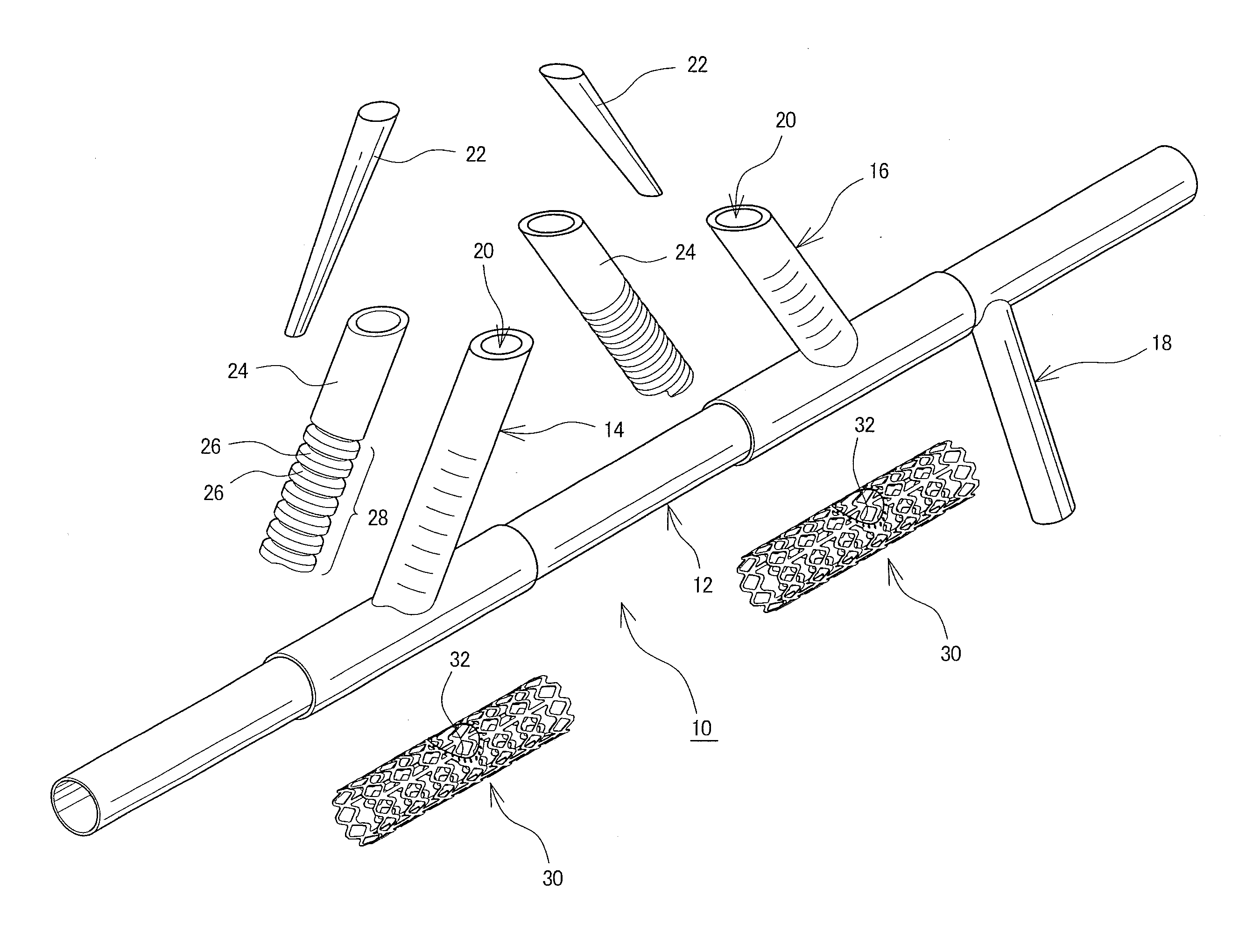
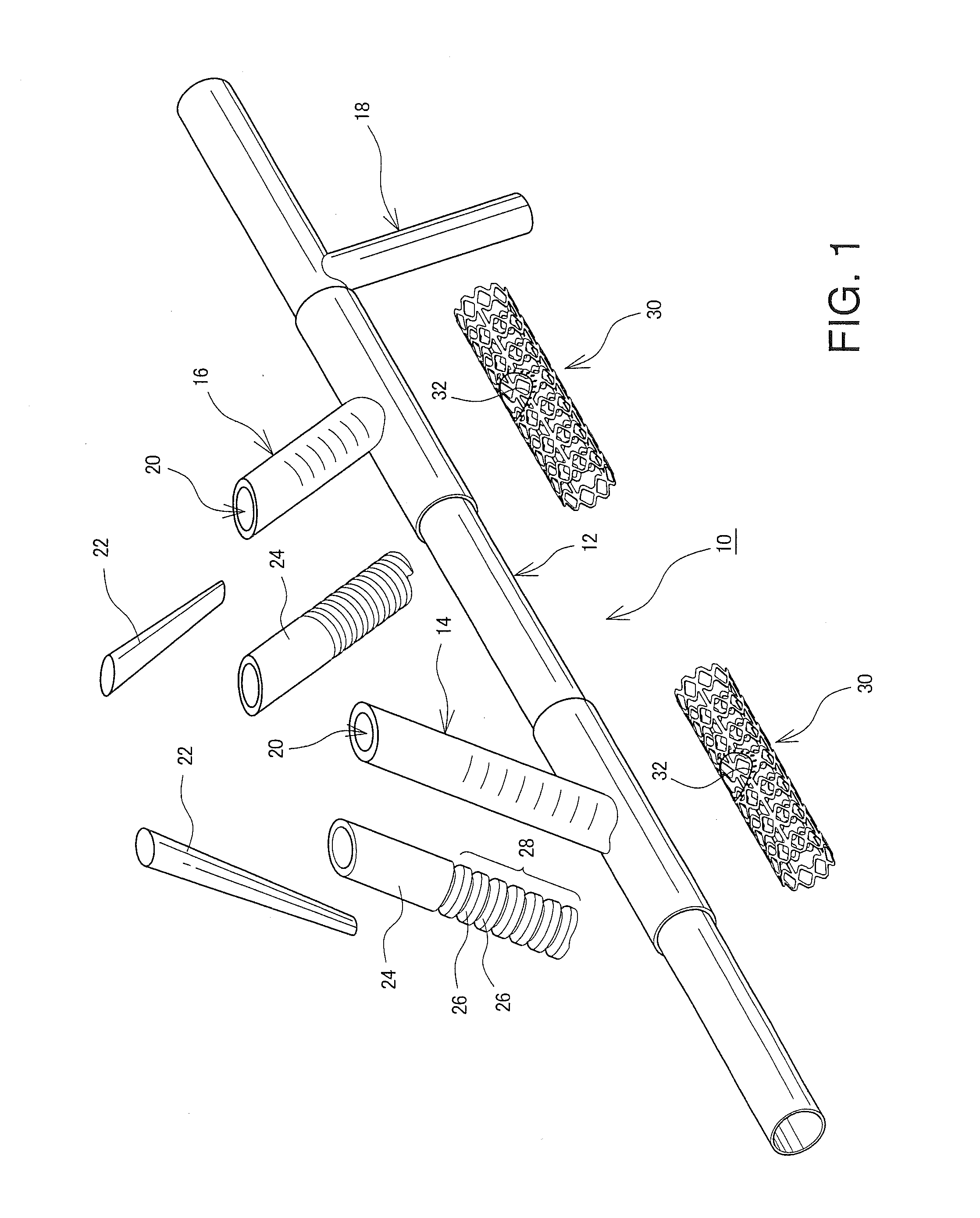
[0018]A preferred embodiment of the present invention will now be described with reference to the drawings. FIG. 1 is a perspective diagram showing an example configuration of an artificial blood vessel 10 having an access port. The artificial blood vessel 10 is used in an extracorporeal blood circulation treatment such as hemodialysis and apheresis treatment in which, after the blood is extracted to the outside of the body and a predetermined process is performed, the blood is again introduced into the body. The artificial blood vessel 10 comprises a trunk portion having both ends connected to a blood vessel, in particular, the vein, and which bridges the vein, and branch portions 14, 16, and 18 branched from the trunk portion 12. Two branch portions 14 and 16 form connection points with an extracorporeal blood circuit for extracting blood to the outside of the body or for introducing fluid such as blood into the body, and the other branch portion 18 forms a shunt to be connected t...


PUM


Abstract

An artificial blood vessel has a trunk portion which forms a part of the blood vessel and also has branch portions which are branched from the trunk portion. The branch portions are provided with access ports into which a needle, for discharging liquid out of a human body or introducing the liquid into the human body, is inserted. Tubular reinforcement members integrated with the blood vessel wall of the trunk portion are disposed at positions of the trunk portion, the positions being those from which the branch portions are branched, and at portions adjacent to the positions of the trunk portion. A lateral force at the time of needle insertion is borne by the reinforcement member, and this prevents the trunk portion from deforming. Thus, the configuration prevents the artificial blood vessel from deforming due to a force applied when a needle for discharging liquid from a human body or introducing the liquid into the human body is inserted into an access port of the artificial blood vessel.

Description

TECHNICAL FIELD[0001]The present invention relates to an artificial blood vessel, and in particular, to a structure of an artificial blood vessel.BACKGROUND ART[0002]In extracorporeal blood circulation treatments in which blood of a patient is temporarily extracted from the body and then returned into the body, such as hemodialysis and apheresis treatment, it is necessary to highly frequently insert a needle into the blood vessel. When the needle is highly-frequently inserted into the blood vessel, there are cases where an aneurysm may be formed or vasoconstriction may be caused. A blood access (blood vessel reaching method) has been proposed which can reduce the number of needle insertions into the blood vessel and which uses an indwelling device. Patent Document 1 discloses a blood access in which a blood chamber connected with the blood vessel by a cannula is equipped with a diaphragm, a needle is inserted into the diaphragm, and introduction of blood or the like into the blood v...

Claims


Application Information

Patent Timeline
Patent Type & Authority Applications(United States)
IPC IPC(8): A61F2/856A61F2/07
CPCA61F2/064A61F2002/061A61M1/3655A61M39/0208A61F2002/067A61M2039/0258A61F2/856A61F2/06A61M39/0247A61F2/02A61F2/04
Inventor ASANO, TAKUJIYOKOYAMA, DAISUKEKINOSHITA, YOSHIHIKO
Owner NIKKISO COMPANY
Why Eureka
Try Eureka