Burner assembly

a technology of burners and components, applied in the direction of burners, hot gas positive displacement engine plants, combustion processes, etc., can solve the problems of small drop formation and less effective penetration, and achieve the effect of narrowing the radial fuel profil

Inactive Publication Date: 2013-05-02
SIEMENS AG
View PDF5 Cites 36 Cited by
  • Summary
  • Abstract
  • Description
  • Claims
  • Application Information

AI Technical Summary

Benefits of technology

[0059]If injection of the fuel takes place for example along a single helical peripheral line and this peripheral line runs along a flow line of the swirled air flow, a regular radial fuel profile can be achieved with the same full jet nozzle diameters. This embodiment can be advantageous when an alternating periphery-based fuel distribution is required with the greatest possible shift of the time delay spectrum. The arrangement of different full jet nozzle diameters here allows different radial fuel profiles to be set, with regular radial profiles being considered advantageous.
[0060]Provision can advantageously be made for the diameters of the full jet nozzles arranged along the at least one helical peripheral line to be configured in such a manner that the diameters increase in the flow direction. This embodiment of the invention is advantageous, when the radial profile is to be homogenized by enrichment of the region close to the axis.
[0061]It can also be considered advantageous for t

Problems solved by technology

With pressure swirl nozzles a higher preliminary pressure causes

Method used


Image

  • Burner assembly
  • Burner assembly
  • Burner assembly

Examples


Embodiment Construction

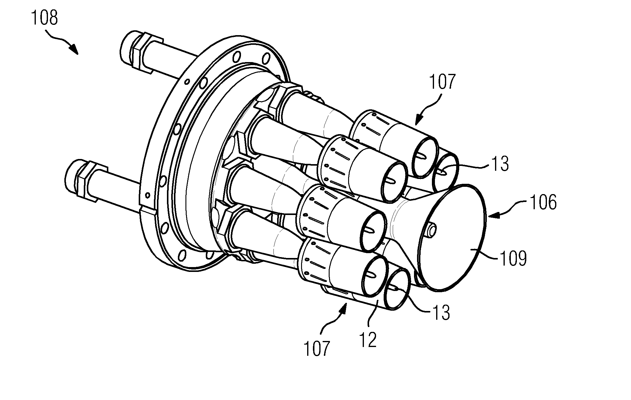
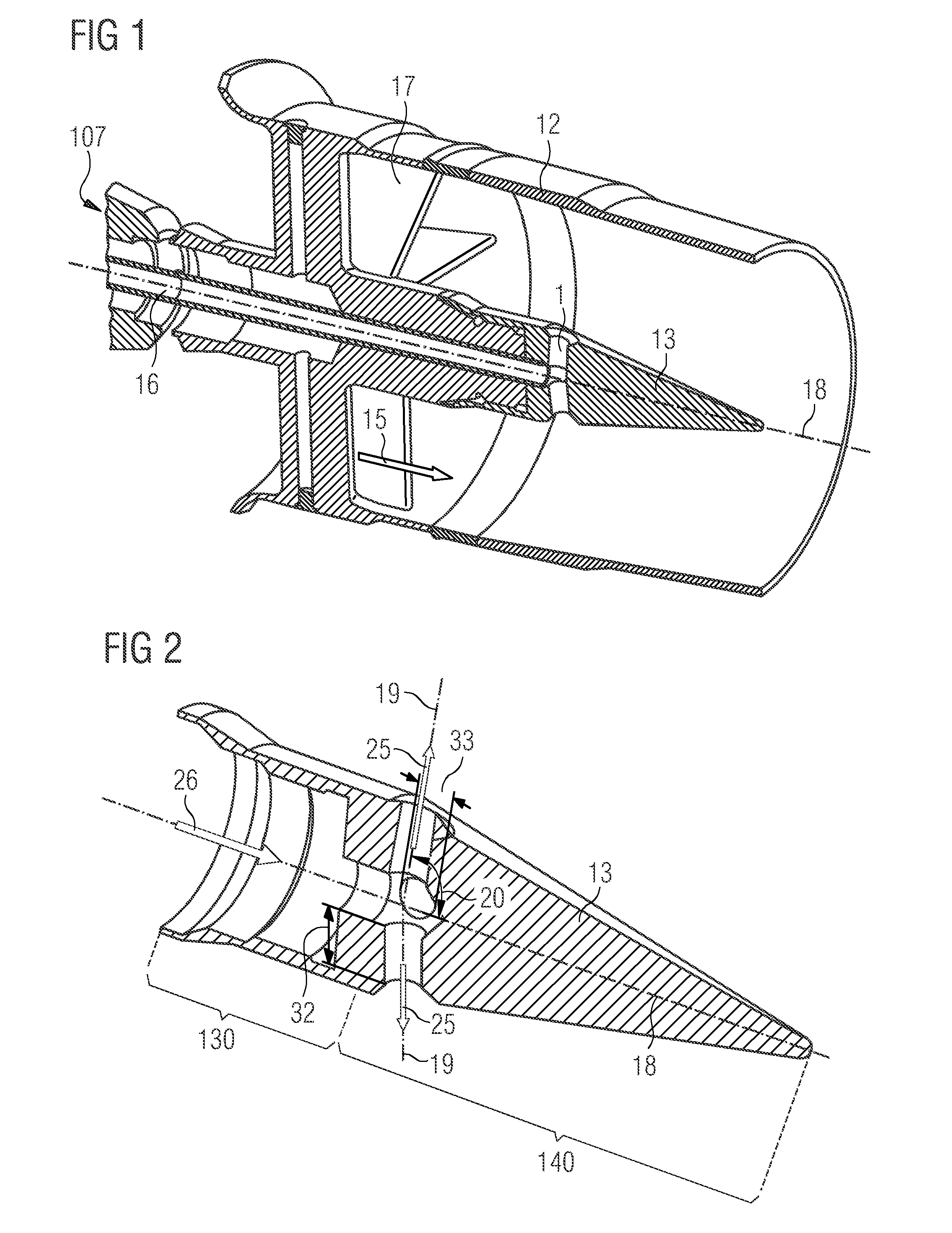
[0088]FIG. 1 shows a detail of an inventive burner assembly in the region of a main burner 107. Swirl blades 17 are arranged around the lance in the housing 12 of the main burner 107. The swirl blades 17 are arranged along the periphery of the lance in the housing 12. The swirl blades 17 direct a compressor air flow 15 into the part of the burner 107 leading to a combustor. The air is made to swirl by the swirl blades 17. The lance also comprises a fuel channel 16. The burner 107 further comprises an attachment 13 on the side leading to a combustor. The attachment 13 can be welded or screwed to the lance for example. The fuel nozzles are preferably arranged downstream of the swirl blades 17 in the attachment 13 and are thus connected for flow purposes to the fuel channel 16, shown here as an oil channel. The inventive burner assembly preferably comprises eight such main burners 107 arranged in a circle (see FIG. 12). The main burners 107 here are arranged around a pilot burner (see ...


PUM


Abstract

A burner assembly for a gas turbine is provided. The burner assembly has a combustor, a centrally arranged pilot burner and plurality of main burners surrounding the pilot burner. Each main burner has a cylindrical housing having a lance which is centrally arranged therein and has a fuel channel for liquid fuel. The lance is supported on the housing by swirl blades and an attachment is arranged on the lance in the direction of the combustor. The liquid fuel nozzle is arranged in the attachment downstream of the swirl blades and connected to the fuel channel. For the improved mixing of the fuel with the air, the liquid fuel nozzle is designed as a full jet nozzle and the full jet nozzle has a length and a diameter, the ratio of the length to the diameter is at least 1.5.

Description

CROSS REFERENCE TO RELATED APPLICATIONS[0001]This application is the US National Stage of International Application No. PCT / EP2011 / 061101 filed Jul. 1, 2011 and claims the benefit thereof. The International Application claims the benefits of European application No. 10168107.0 filed Jul. 1, 2010, both of the applications are incorporated by reference herein in their entirety.FIELD OF THE INVENTION[0002]The present invention relates to a burner assembly for a gas turbine having at least one combustor, wherein the burner assembly comprises a centrally arranged pilot burner and a number of main burners surrounding the pilot burner, wherein each of the main burners comprises a cylindrical housing having a lance which is centrally arranged therein and has a fuel channel for liquid fuel, wherein the lance is supported on the housing by means of swirl blades and an attachment is arranged on the lance in the direction of the combustor, wherein at least one liquid fuel nozzle is arranged in ...

Claims


Application Information

Patent Timeline
IPC IPC(8): F23R3/34
CPCF23C2900/07021F23R3/343F23R3/286F23D11/38
Inventor BODE, SIEGFRIEDFOX, TIMOTHY A.GRIEB, THOMASHASE, MATTHIASMEISL, JURGENPFADLER, SEBASTIAN
Owner SIEMENS AG
Why Eureka
Try Eureka