

Active Prop Rotor Stability System
- Summary
- Abstract
- Description
- Claims
- Application Information
AI Technical Summary
Benefits of technology
Problems solved by technology
Method used
Image

Examples
Embodiment Construction
[0021]Illustrative embodiments of the system and method are provided below. It will of course be appreciated that in the development of any actual embodiment, numerous implementation-specific decisions will be made to achieve the developer's specific goals, such as compliance with assembly-related and business-related constraints, which will vary from one implementation to another. Moreover, it will be appreciated that such a development effort might be complex and time-consuming, but would nevertheless be a routine undertaking for those of ordinary skill in the art having the benefit of this disclosure.
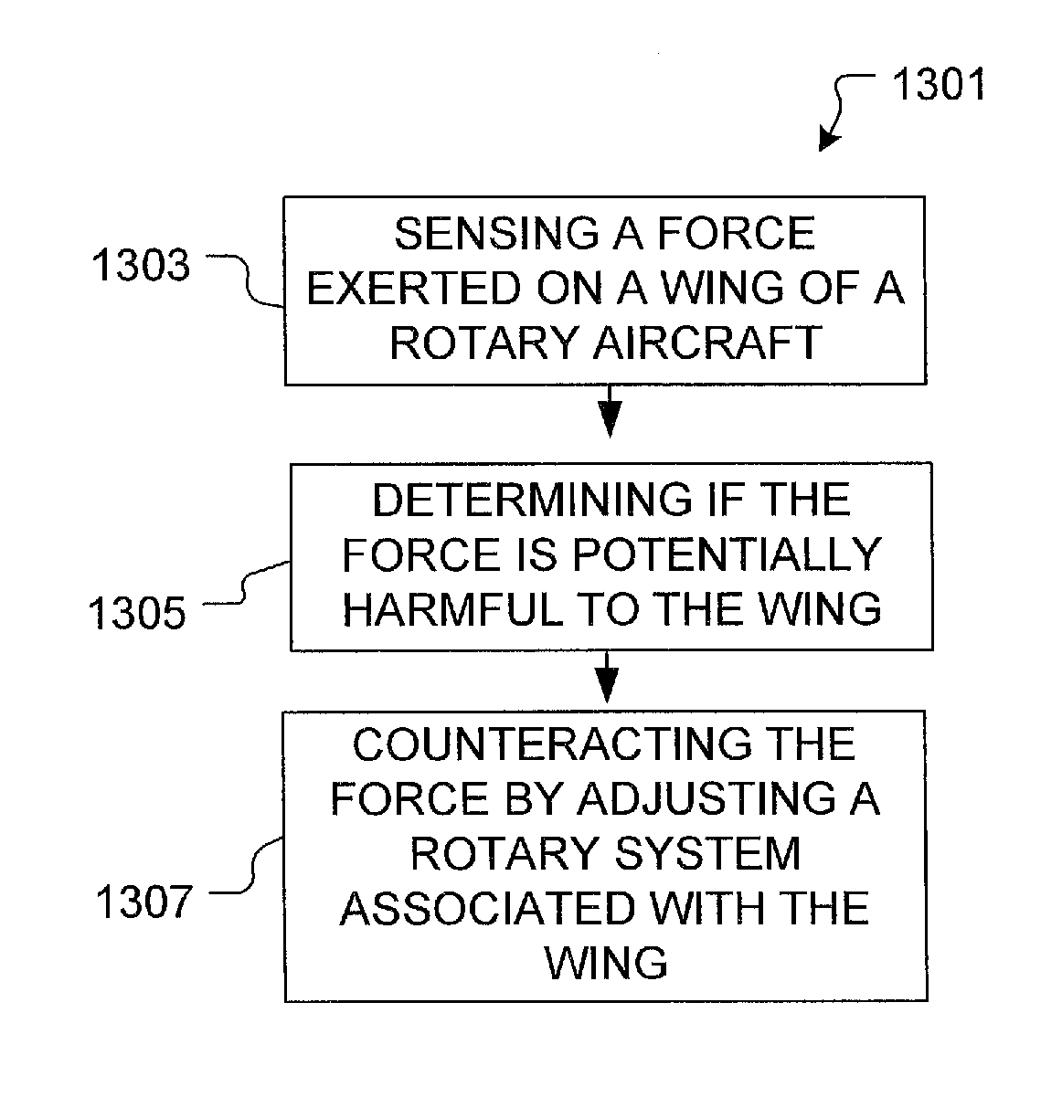
[0022]The system of the present application overcomes common disadvantages associated with conventional rotary systems. In particular, the rotary aircraft includes a control system having one or more sensors configured to sense rotational and bending movement on a wing of the aircraft, and configured to adjust the rotary blades accordingly to counteract any wing movement. The system ...
PUM
 Abstract
Description
Claims
Application Information