Encoding method, decoding method, encoding device, decoding device, program, and recording medium

a decoding method and a technology of a decoding device, applied in the field of encoding or decoding signal sequences, can solve the problems of block noise, perceived noise, equivalent to musical noise, etc., and achieve the effect of reducing quantization error, musical noise and the like, and reducing quantization error

Active Publication Date: 2013-05-02
NIPPON TELEGRAPH & TELEPHONE CORP
View PDF6 Cites 0 Cited by
  • Summary
  • Abstract
  • Description
  • Claims
  • Application Information

AI Technical Summary

Benefits of technology

[0014]In encoding, since index information indicating a group that includes a plurality of gradient coefficients is output to adjust the quantized values of a plurality of samples, the quantization error in decoding can be reduced, and as a result musical noise and the like can be reduced.
[0015]In decoding, since a plurality of decoded values are adjusted by using a group that includes a plurality of gradient coefficients indicated by index information, the quantization error can be reduced, and as a result musical noise and the like can be reduced.

Problems solved by technology

If the input signals are acoustic signals, these variations may be perceived as noise which is known as musical noise.
If the input signals are video signals, block noise, which is equivalent to musical noise in the acoustic signals, may occur.

Method used


Image

  • Encoding method, decoding method, encoding device, decoding device, program, and recording medium
  • Encoding method, decoding method, encoding device, decoding device, program, and recording medium
  • Encoding method, decoding method, encoding device, decoding device, program, and recording medium

Examples


example 1

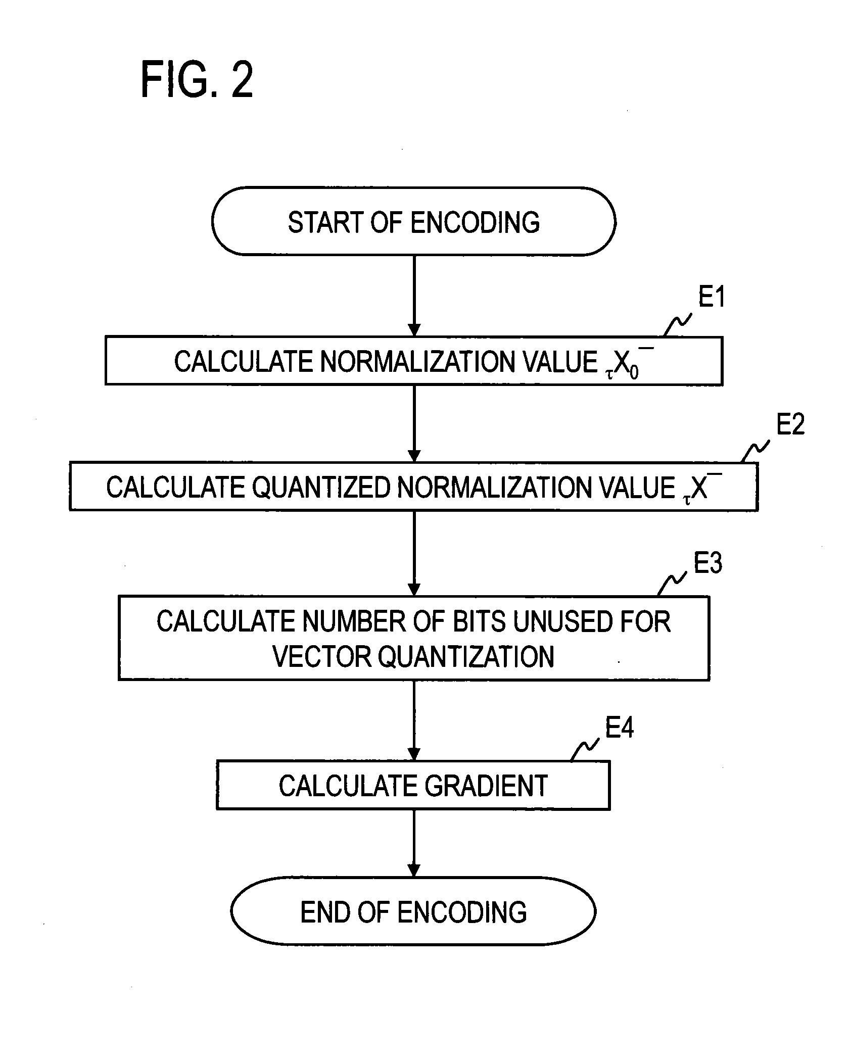
[0055][Example 1 of Step E4]

[0056]The gradient calculator 116 in this example executes the steps shown in FIGS. 3 and 4 to write index information idx indicating the row number of the selected gradient coefficient vector in the unused bit region.

[0057]The gradient calculator 116 initializes the i, h, and u values to 0, H, and U, respectively (step E41), and proceeds to step E42. When C0 indicates the number of samples in the sub-band, H indicates the number of sub-bands in a single frame that has been vector-quantized in the vector quantizer. When C0 indicates the number of samples, L, in a single frame, H becomes 1.

[0058]The gradient calculator 116 compares i with G (G=L / C0) (step E42) and, if i43 or, if i4. When C0 indicates the number of samples in the sub-band, G indicates the total number of sub-bands in a single frame. When C0 indicates the number of samples, L, in a single frame, G=1. When δ is compared with η, the comparison method is not limited, and any comparison method t...

example 2

[0069][Example 2 of Step E4]

[0070]Step E4 may be executed as described below, for example, as illustrated in FIGS. 3 and 4.

[0071]After steps E41 to E45 are executed, if it is decided in step E45 that flg(b)>0 is not satisfied (flg(b)=0 is satisfied), the gradient calculator 116 increments i by 1 (step E421) and proceeds to step E42. If it is decided in step E45 that flg(b)>0 is satisfied (flg(b)=η is satisfied), the gradient calculator 116 sets MMAX=1 and a=1 (step E48′) and proceeds to step E46.

[0072]In step E46, the gradient calculator 116 compares u−h with 0 (equivalent to comparing u with h); and if u−h>0 is satisfied (step E46), mMAX=3 and a=2 are set (step E47), and the processing proceeds to step E49. If u−h>0 is not satisfied, the processing proceeds to step E49 without changing MMAX and “a”. The remaining part of the processing is the same as in Example 1 of step E4. The gradient calculator 116 here outputs index information idx that can be expressed with the bits assigned ...

example 3

[0073][Example 3 of Step E4]

[0074]In Examples 1 and 2 of step E4, the following calculation may be made instead of Equation (2).

eMIN=Σj=0C0−1∥X(b·C0+j)|−|{circumflex over (X)}(b·C0+j)∥

In Examples 1 and 2 of step E4, the following calculation may be made instead of Equation (3).

e=Σj=0C0−1∥X(b·C0+j)|−γm·|{circumflex over (X)}(b·C0+j)∥

The description of [Examples of step E4] ends here.

[0075]The code (bit stream) corresponding to an modified vector quantization index that includes the vector quantization index and the index information idx written in the unused bit region is sent to the decoding device 12.

[0076](Decoding)

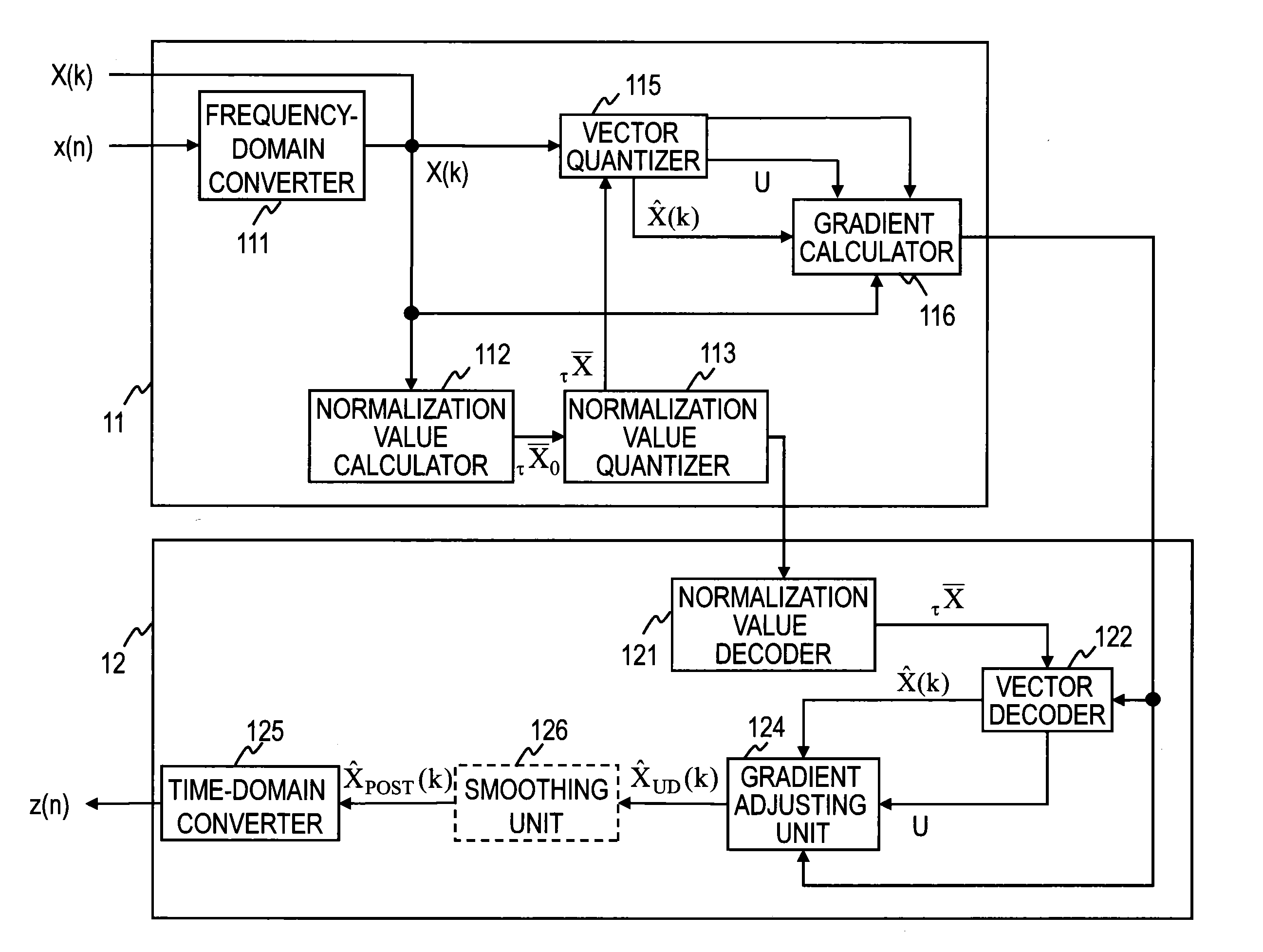
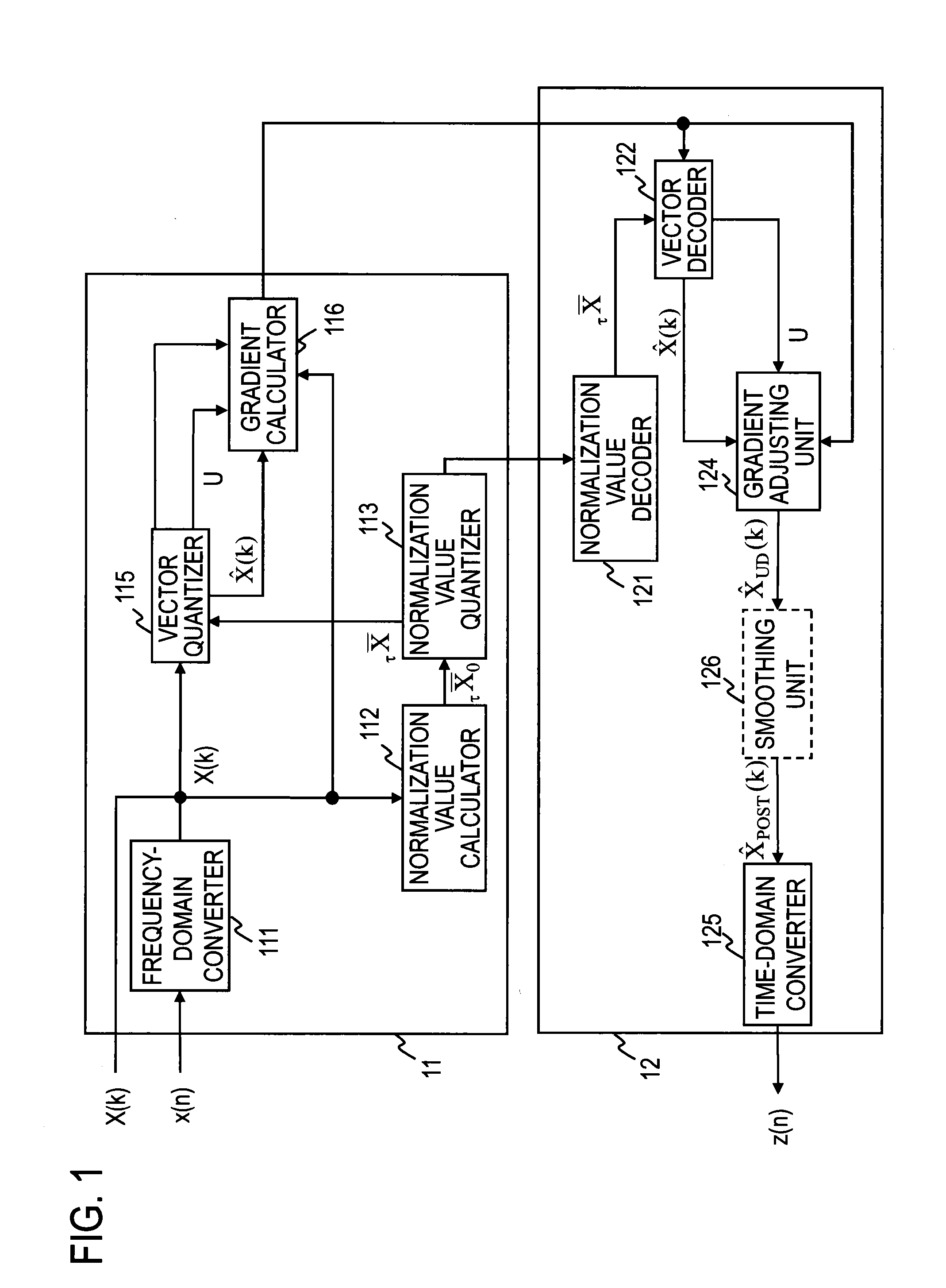
[0077]The decoding device 12 executes the steps of a decoding method illustrated in FIG. 5.

[0078]The normalization value decoder 121 obtains a decoded normalization value τX− corresponding to the normalization-value quantization index input to the decoding device 12 (step D1). The decoded normalization value τX− is sent to the vector decoder 122.

[0079]It is assumed that...


PUM


Abstract

A plurality of samples are vector-quantized to obtain a vector quantization index and quantized values; bits are assigned in a predetermined order of priority based on auditory perceptual characteristics to one or more sets of sample positions among a plurality of sets of sample positions, each set having a plurality of sample positions and being given an order of priority based on the auditory perceptual characteristics, the number of bits not being larger than the number of bits obtained by subtracting the number of bits used for a code corresponding to the vector quantization index from the number of bits assigned for the code corresponding to the vector quantization index; and index information indicating a group of coefficients that minimizes the sum of the error between the value of each sample included in each of the sets of sample positions to which the bits are assigned and the value obtained by multiplying the quantized value of each sample included in the set of sample positions by a coefficient corresponding to the position of the sample, of all the sample positions included in the set of sample positions, is output.

Description

TECHNICAL FIELD[0001]The present invention relates to a technology for encoding or decoding signal sequences of acoustic signals, video signals, and other signals, such as voice and music, by vector quantization.BACKGROUND ART[0002]In an encoding device disclosed in Patent Literature 1, an input signal is first divided by a normalization value to perform normalization. The normalization value is quantized, and a quantization index is generated. The normalized input signal is vector-quantized, and an index of a representative quantization vector is generated. The generated quantization index and the generated representative quantization vector are output to a decoding device. The decoding device decodes the quantization index and generates a normalization value. The index of the representative quantization vector is also decoded, and a sample sequence is generated. A sequence of the values obtained by multiplying each sample in the generated sample sequence by the normalization value...

Claims


Application Information

Patent Timeline
Patent Type & Authority Applications(United States)
IPC IPC(8): H03M7/00G10L19/032G10L19/035G10L19/038
CPCH03M7/00G10L19/032
Inventor FUKUI, MASAHIROSASAKI, SHIGEAKIHIWASAKI, YUSUKEKOYAMA, SHOICHITSUTSUMI, KIMITAKA
Owner NIPPON TELEGRAPH & TELEPHONE CORP
Why Eureka
Try Eureka