LED lamp

a technology of led lamps and led bulbs, which is applied in the field of led lamps, can solve the problems of short lamp life of less than 2000 hours and the need to replace them frequently, and achieve the effect of increasing the efficiency of such lights and prolonging the lamp replacement interval

Inactive Publication Date: 2013-05-02
OSRAM GMBH
View PDF5 Cites 3 Cited by
  • Summary
  • Abstract
  • Description
  • Claims
  • Application Information

AI Technical Summary

Benefits of technology

[0004]The object of the present invention is to lengthen the lamp replacement interval duration and to increase the efficiency of such lights.
[0008]It is preferable if the LED is an Oslon® LED (1 W), which is produced by the applicant. It offers good efficiency with good light quality.
[0012]To improve the heat conduction, in a first variant, the heat sink can consist of brass and can be sectionally screwed via a fine thread into a recess of the light housing. The heat sink is thus in good thermal contact with the light housing.
[0014]To improve the heat transfer from the brass sleeve via the recess to the light housing, a heat conduction paste can be arranged between an outer wall of the brass sleeve and an inner wall of the recess.
[0017]Two strands, which are connected in parallel, of multiple, in particular respectively 12 LEDs, can preferably be supplied by a power source (preferably 700 mA, 35 W) via a power equalization circuit. Thermal divergence of the two strands is thus prevented.
[0018]Each strand can be operated with 350 mA, and a power equalization circuit can be provided, which prevents thermal divergence of the strands.

Problems solved by technology

Such lights have the disadvantage of a short lifetime of the lamps of less than 2000 hours, which makes it necessary to replace them frequently.

Method used


Image

  • LED lamp
  • LED lamp
  • LED lamp

Examples


Embodiment Construction

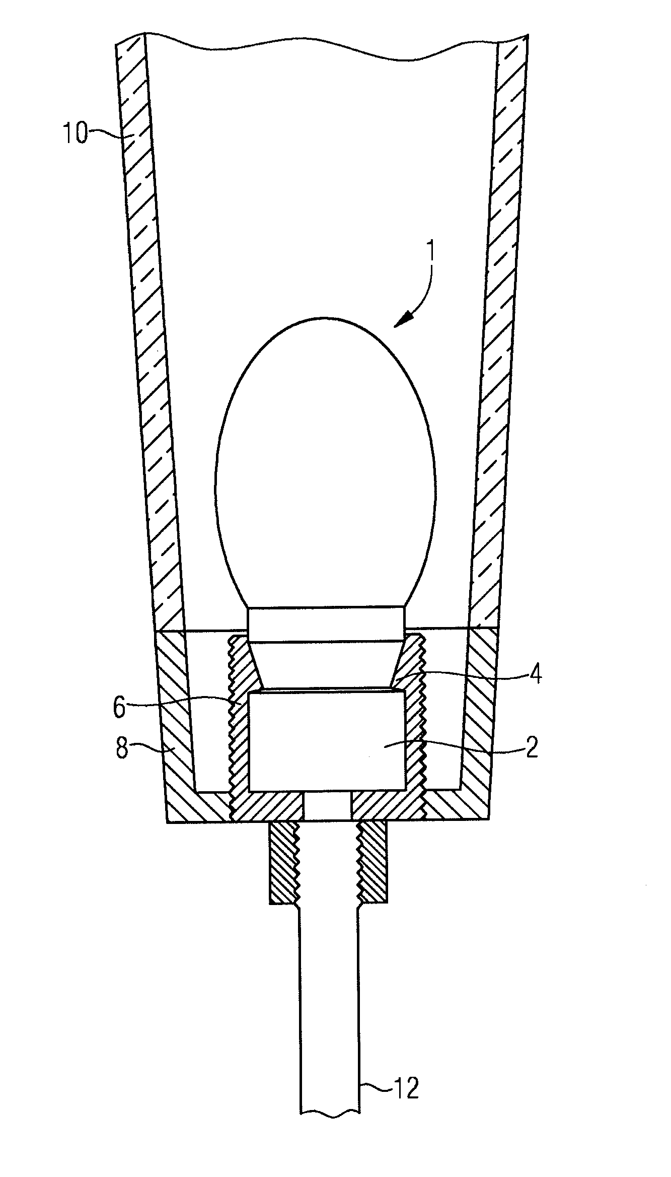
[0024]FIG. 1 shows a detail of a light according to the prior art having a halogen pin-base lamp 1 in an illustration in partial section. The halogen pin-base lamp 1 is a Halopin® lamp of the applicant. It has a power consumption of 25 W and bears the designation G9 according to the IEC 60432 standard. The halogen pin-base lamp 1 is inserted into a ceramic socket 2, which corresponds to the same standard.

[0025]The ceramic socket 2 is inserted into a cup-shaped plastic mount 6 and secured therein via a clamp mount 4.

[0026]The plastic mount 6 is inserted into a metallic cup-shaped housing section 8 of the light and fastened therein. The plastic mount 6 has an external thread, which holds a glass lampshade 10, approximately in the form of a truncated cone, which is used as a light diffuser, and which is only partially shown in FIG. 1. The lampshade 10 is placed on a peripheral edge of the housing section 8.

[0027]On a side of the housing section 8 opposite the lampshade 10, a metallic c...


PUM


Abstract

A light having a lamp housing (8) having a receptacle (6), which receptacle is adapted for receiving a socket (2) for a halogen pin-base lamp (1), wherein a heat sink (102) having thermal contact with the lamp housing (8), and on which an LED (101) is fastened, is at least sectionally received in the receptacle (6).

Description

TECHNICAL AREA[0001]The invention is directed to a light which is provided for one or more sockets for halogen pin-base lamps.PRIOR ART[0002]Lights with halogen pin-base lamps, which are inserted into corresponding sockets, are known from the prior art. The halogen pin-base lamp and the socket can correspond, e.g., to the IEC 60432 standard G9. The socket is inserted into a receptacle of a light housing.[0003]Such lights have the disadvantage of a short lifetime of the lamps of less than 2000 hours, which makes it necessary to replace them frequently.SUMMARY OF THE INVENTION[0004]The object of the present invention is to lengthen the lamp replacement interval duration and to increase the efficiency of such lights.[0005]This object is achieved by a light according to patent claim 1.[0006]Particularly advantageous embodiments are found in the dependent claims.[0007]The light according to the invention has a light housing having a receptacle, which receptacle is suitable for receiving ...

Claims


Application Information

Patent Timeline
Patent Type & Authority Applications(United States)
IPC IPC(8): F21V19/00F21V29/00F21V15/01
CPCF21S8/065F21V19/0055F21V29/004F21Y2101/02F21V29/89F21V15/01F21V19/0005F21V29/70F21Y2111/007F21Y2115/10F21Y2107/40F21V29/507
Inventor PETER, MATTHIAS
Owner OSRAM GMBH
Why Eureka
Try Eureka