Method Using a Blanking Signal to Reduce the Leakage Transmitter-Receiver

Active Publication Date: 2013-05-02
TELEFON AB LM ERICSSON (PUBL)
View PDF7 Cites 8 Cited by
  • Summary
  • Abstract
  • Description
  • Claims
  • Application Information

AI Technical Summary

Benefits of technology

[0041]According to a further embodiment of the present invention the further receiver comprises a Satellite Positioning System receiver and in particular a Global Positioning System receiver. This may provide the advantage that the described concept for reducing self interference within a communication end device can be applied to a type of user equipment, which is widely-used by many users. Therefore, there may be a large benefit when implementing the described solution for efficientl

Problems solved by technology

However, such combined communication end devices may also exhibit certain shortcomings such as increased power consumption and a reduced performance.
One marked disadvantage inherent in many combined SPS receiver and radio communication device is the decreased performance of the SPS receiver in particular when a radio transmitter of the radio communication device is active.
Although the radio transmitter of the radio communication device and the SPS (radio) receiver typically operate in completely different frequency bands, the described self interference is often troublesome because

Method used


Image

  • Method Using a Blanking Signal to Reduce the Leakage Transmitter-Receiver
  • Method Using a Blanking Signal to Reduce the Leakage Transmitter-Receiver
  • Method Using a Blanking Signal to Reduce the Leakage Transmitter-Receiver

Examples


Embodiment Construction

[0059]The illustration in the drawing is schematically.

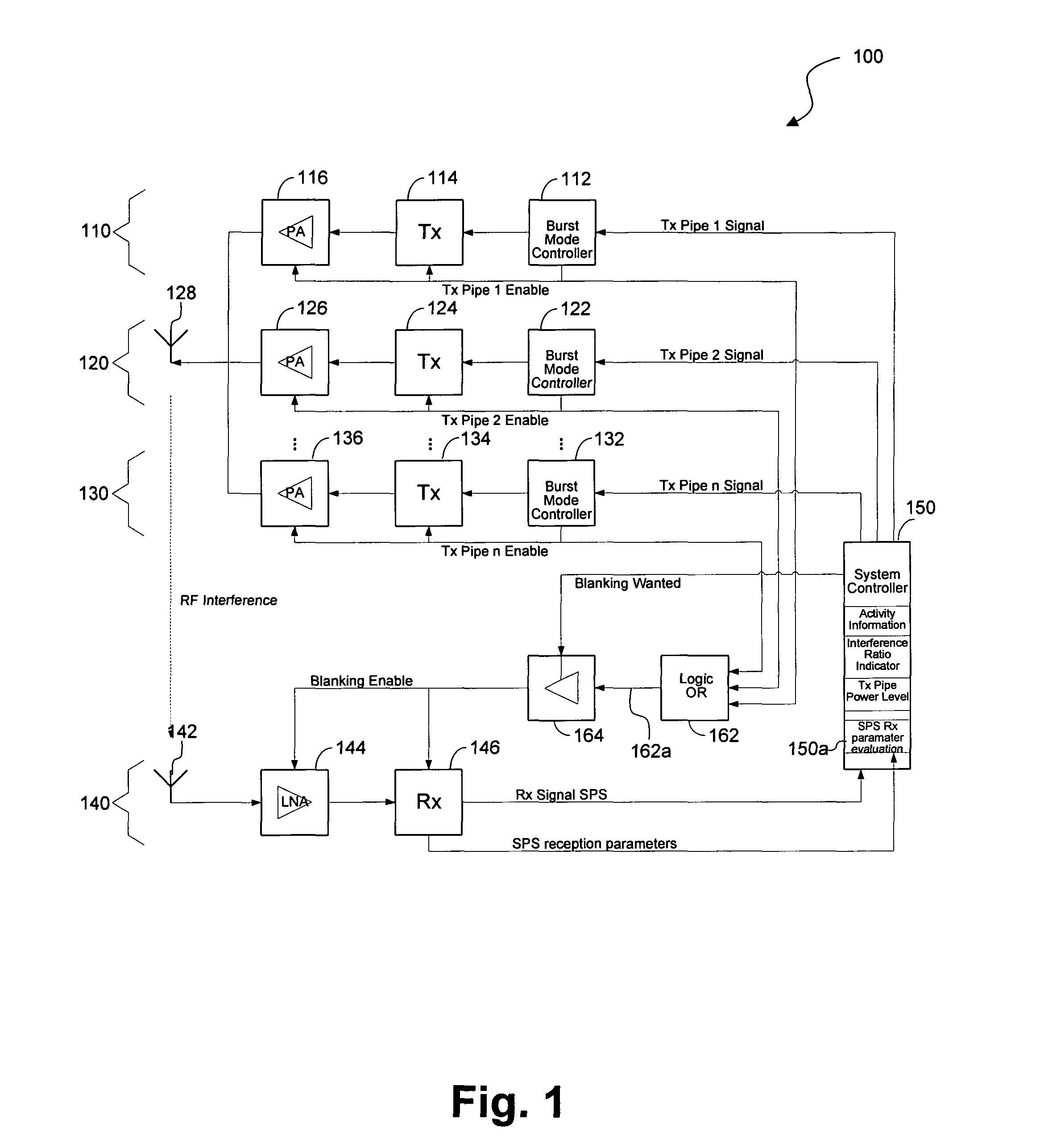
[0060]FIG. 1 shows a structural diagram of a communication end device 100 in accordance with an embodiment of the invention. The communication end device 100 is a multiband and multimode user equipment. Specifically, apart from a cellular radio transceiver with a cellular transmitter and a cellular receiver the communication end device 100 comprises a further receiver 140. According to the embodiment described here the further receiver is a satellite positioning system (SPS) receiver 140.

[0061]The communication end device 100 comprises a control unit 150, which is connected both to the transmitter of the cellular radio transceiver and to the SPS receiver 140. The control unit is configured for controlling the operation of the cellular transmitter and in particular of the SPS receiver 140.

[0062]As can be seen from FIG. 1, the cellular transmitter comprises a plurality of cellular transmission pipes. In FIG. 1 there are shown thre...


PUM


Abstract

It is described a communication end device comprising (a) a radio transceiver comprising a receiver for receiving radio signals from a transmitting network entity of a cellular telecommunication network and a transmitter (110, 120, 130) for transmitting radio signals to a receiving network entity of the cellular telecommunication network, (b) a further receiver (140) for receiving a further radio signal, and (c) a control circuit (150, 162, 164), which is coupled to the radio transceiver and to the further receiver (140). The control circuit (150, 162, 164) is configured for generating a control signal for controlling the operation of the further receiver (140). Thereby, the control signal is based on a synchronization signal being related to a time dependent transmission scheme of the transmitter (110, 120, 130) and on an information about the current operational state of the radio transceiver. It is further described a method for controlling the operation of such a communication end device (100) and a program element and a computer-readable medium having stored such a program element, which is adapted for controlling and/or for carrying out this operation control method.

Description

FIELD OF THE INVENTION[0001]The present invention relates to the technical field of mobile communication end devices, which comprise a transmitter and at least two receivers, wherein the two receivers are capable of receiving two different types of radio signals. Specifically, the present invention relates to a mobile communication end device comprising a transmitter and at least two receivers and to a method for operating such a mobile communication end device, wherein self interference between the transmitter and at least one of the two receivers can be minimized. Further the present invention relates to a program element and to a computer-readable medium with such a program element, which is adapted for controlling and / or for carrying out the described method.BACKGROUND OF THE INVENTION[0002]The use of portable personal communication devices, such as cellular phones, Personal Digital Assistant (PDA), a notebook computer and / or any other movable communication devices being configu...

Claims


Application Information

Patent Timeline
IPC IPC(8): H04W88/06H04B1/38
CPCH03G3/3078H04W88/06H04B1/3805H04B1/525
Inventor NEUMANN, MARKUS
Owner TELEFON AB LM ERICSSON (PUBL)
Why Eureka
Try Eureka