Methods and Apparatuses for Charging of Electric Vehicles

a technology for electric vehicles and charging devices, applied in the direction of electric energy management, navigation instruments, and battery arrangements, etc., can solve the problems of limited demand for electric vehicles, limited distance between pure electric vehicles and hybrid or gasoline-powered counterparts, and inability to commercially available charging stations

Active Publication Date: 2013-05-02
ZECO SYST
View PDF6 Cites 348 Cited by
  • Summary
  • Abstract
  • Description
  • Claims
  • Application Information

AI Technical Summary

Benefits of technology

[0024]Described herein are also implementations of various techniques of a method for managing an electric vehicle charging station. The method may include an electric vehicle charging station receiving a charge control signal from a server. The charging control signal adjusts the duty cycle of a charging current. The charging station may then enable a charge transfer based on the charging current with the adjusted duty cycle. In one implementation, the server may be a cloud server. In one implementation, the server may be a local metering network server. In one implementation, the duty cycle may be determined by a total number of electric vehicles connected to a power grid. In one implementation, the charging current may be a pulse width modulated (PWM) signal. In one implementation, the duty cycle may be increased or decreased incrementally over a specified timeframe. The method may include adjusting the duty cycle based on at least one of the following: a battery temperature of an electric vehicle; a charging current; a current battery charge of an electric vehicle; a length of time since an electric vehicle began charging; a price of electricity; a time of day; a time until an electric vehicle's next use; a weather reading; and an option for econocharging. The method may include adjusting the duty cycle based on at least one of the following parameters: a charging cable rating; a circuit protection rating; a current duty cycle for a charging current; a future power draw from an electric vehicle; a threshold level for aggregate electrical consumption; a threshold level for instantaneous electrical consumption; a local aggregate energy consumption; a maximum allowable charge rate; a minimum allowable charge rate; a microgrid rating; a present power draw from an electric vehicle; a protection fuse rating; a quantity of electricity stored within a microgrid; a total maximum allowable load on a microgrid; an operational limit set by a grid utility; and an option for using green energy.
[0025]Described herein are also implementations of various techniques of a method for managing an electric vehicle charging station. The method may include sending a charging control signal to an electric vehicle charging station, where the charging control signal adjusts the duty cycle of a charging current used in a charge transfer at the electric vehicle charging station. The method may then include receiving a response from the charging station. In one implementation, a cloud server sends the charging control signal. In another implementation, a local metering network sends the charging control signal. In one implementation, the charging control signal may be sent from a cloud server. In one implementation, the charging control signal may be over a local metering network. In one implementation, the duty cycle may be determined by a total number of electric vehicles connected to a power grid. In one implementation, the charging current may be a pulse width modulated (PWM) signal. In one implementation, the duty cycle may be increased or decreased incrementally over a specified timeframe. In one implementation, the charging control signal may be determined based on at least one of the following: a battery temperature of an electric vehicle; a charging current; a current battery charge of an electric vehicle; a length of time since an electric vehicle began charging; a price of electricity; a time of day; a time until an electric vehicle's next use; a weather reading; and an option for econocharging. In one implementation, the charging control signal may be determined based on at least one of the following: a charging cable rating; a circuit protection rating; a duty cycle for a charging current; a future power draw from an electric vehicle; a threshold level for aggregate electrical consumption; a threshold level for instantaneous electrical consumption; a local aggregate energy consumption; a maximum allowable charge rate; a maximum allowable charge rate; a microgrid rating; a present power draw from an electric vehicle; a protection fuse rating; a quantity of electricity stored within a microgrid; a total maximum allowable load on a microgrid; an operational limit set by a grid utility; and an option for using green energy.
[0026]Described herein are also implementations of various techniques of a method for managing an electric vehicle charging station. The method may include sending charging controls signal between electric vehicle charging stations for adjusting a charge transfer for an electric vehicle connected to one of the charging stations. The charging station sending the charging control signal may receive a response from the charging station receiving the charging control signal. In one implementation, the charging control signal may enable or disable the charge transfer at the second charging station. In one implementation, the charging control signal may be sent to a plurality of electric vehicle charging stations. In one implementation, the charging control signal may determine a plurality of charging currents for the plurality of charging stations. In one implementation, the charging control signal may be based on a communication with a grid utility. In one implementation, the charging control signal may be determined based on at least on...

Problems solved by technology

However, while gas stations are located on every street corner, commercially available charging stations are not.
The demand for electric vehicles remains limited by the infrastructure available for supporting the charging of the growing number of cars.
Several problems currently exist in making electric vehicles ideal for personal use.
First, many pure electric vehicles have severe distance limitations in comparis...

Method used


Image

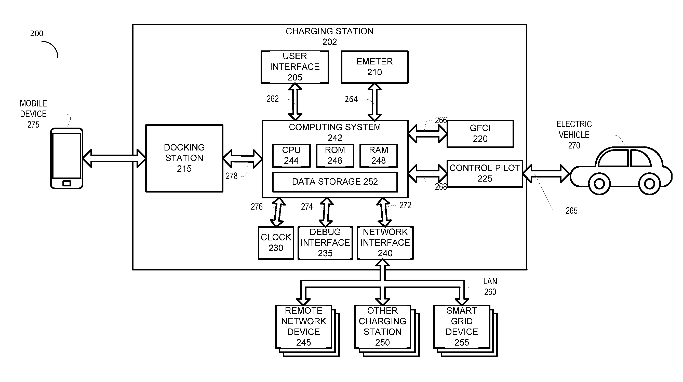
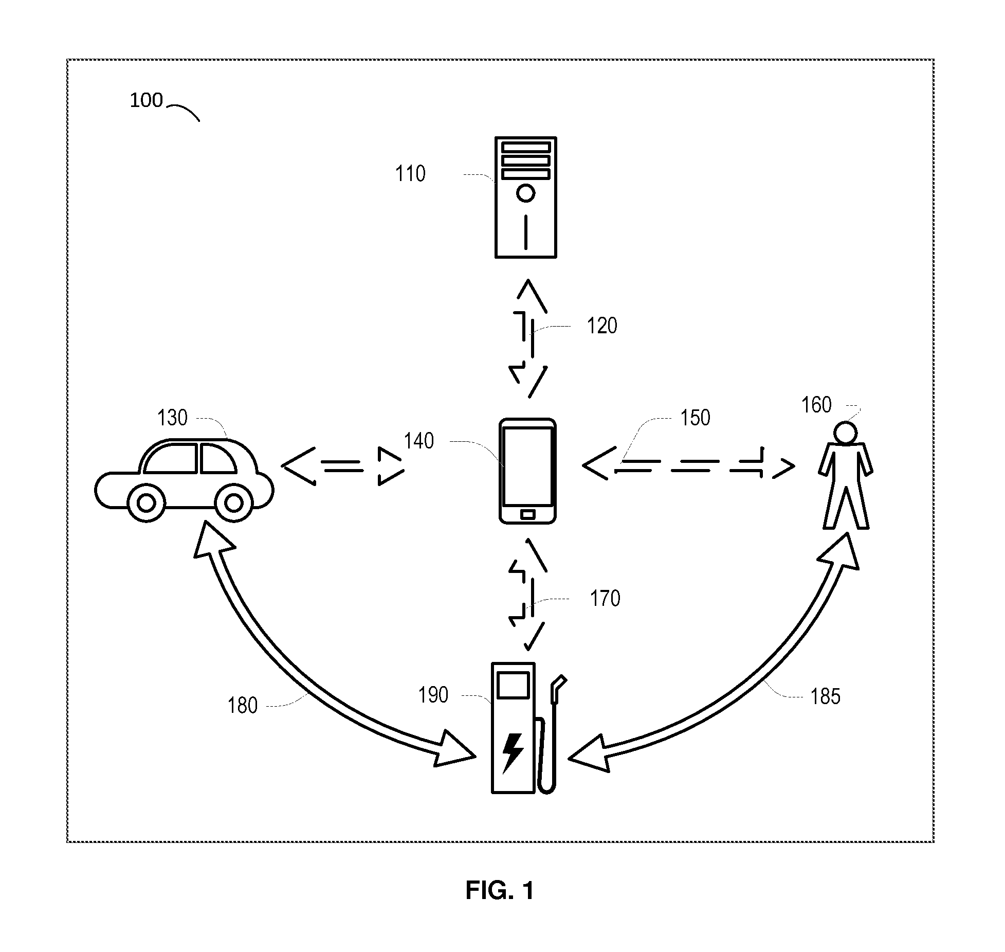
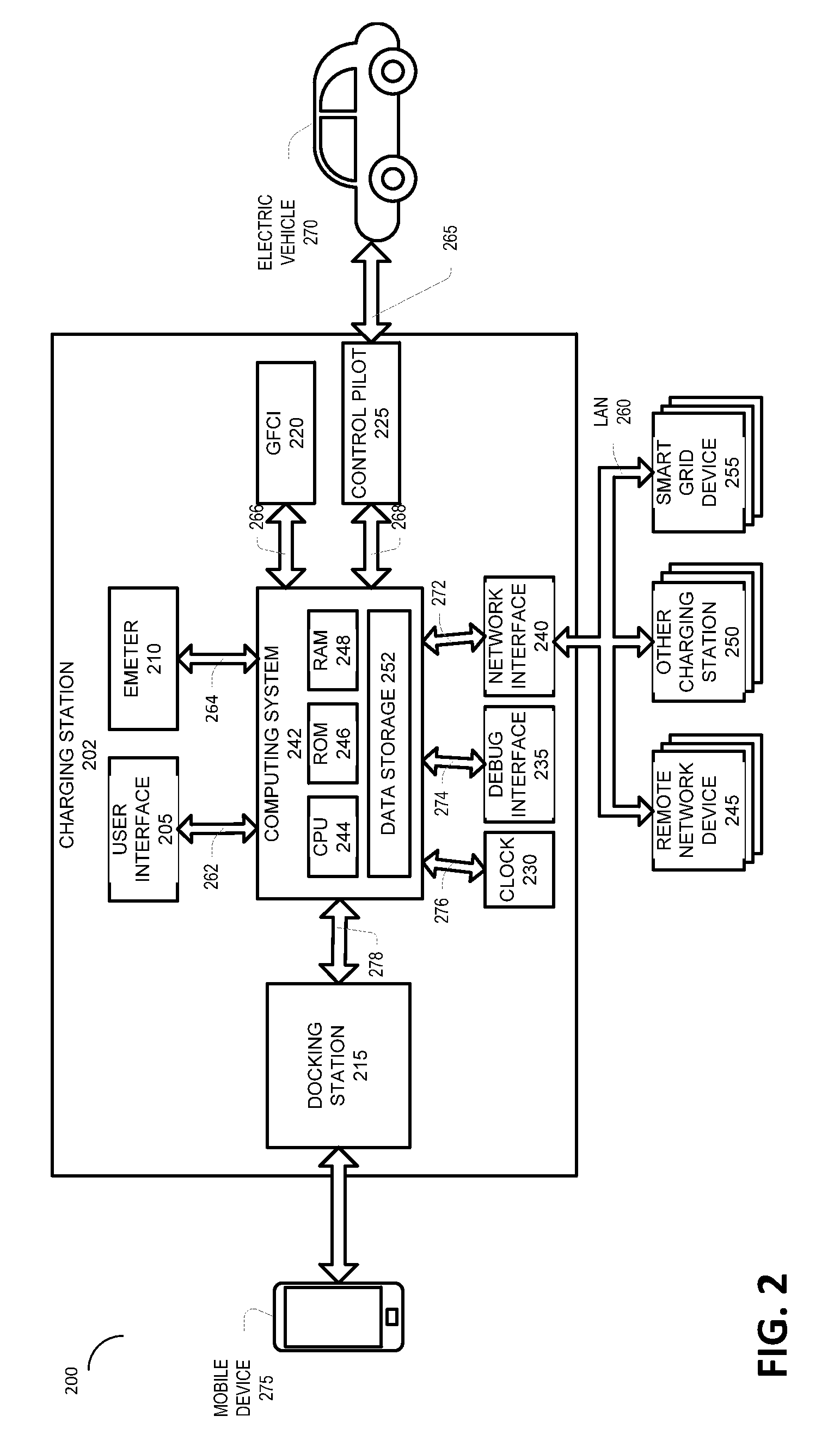
  • Methods and Apparatuses for Charging of Electric Vehicles
  • Methods and Apparatuses for Charging of Electric Vehicles
  • Methods and Apparatuses for Charging of Electric Vehicles

Examples


Embodiment Construction

[0051]The discussion below is directed to certain specific implementations. It is to be understood that the discussion below is only for the purpose of enabling a person with ordinary skill in the art to make and use any subject matter defined now or later by the patent “claims” found in any issued patent herein.

[0052]Reference will now be made in detail to various implementations, examples of which are illustrated in the accompanying drawings and figures. In the following detailed description, numerous specific details are set forth in order to provide a thorough understanding of the claimed invention. However, it will be apparent to one of ordinary skill in the art that the claimed invention may be practiced without these specific details. In other instances, well known methods, procedures, components, circuits, and networks have not been described in detail so as not to unnecessarily obscure aspects of the claimed invention.

[0053]It will also be understood that, although the term...


PUM


Abstract

A method for managing the charging of an electric vehicle. The method includes receiving a request for a charge transfer for an electric vehicle over a network link between an electric vehicle charging station and a cloud server. The network link has a mobile device disposed between the electrical vehicle charging station and the cloud server for facilitating communication between the charging station and the cloud server.

Description

RELATED APPLICATIONS[0001]This application claims the benefit of U.S. provisional patent application Ser. No. 61 / 549,174, filed Oct. 19, 2011, titled Methods and Apparatuses for Controlled Variable Rate Charging of Electric Vehicles and also U.S. provisional patent application Ser. No. 61 / 620,855, filed Apr. 5, 2012, titled Management of Charging Station of Electric-Powered Vehicles Using a Mobile Device. Each of the aforementioned related patent applications is herein incorporated by reference.BACKGROUND[0002]1. Field of Invention[0003]Various technologies and techniques described herein relate to electric vehicles and systems and methods for recharging electric vehicles.[0004]2. Related Art[0005]This section is intended to provide background information to facilitate a better understanding of various technologies described herein. As the section's title implies, this is a discussion of related art. That such art is related in no way implies that it is prior art. The related art ma...

Claims


Application Information

Patent Timeline
IPC IPC(8): G06F1/26H04W4/02H04W4/40
CPCB60L11/1816Y02T10/7291B60L11/184B60L11/1844B60L11/1846B60L11/1848B60L2230/16B60L2230/40B60L2240/12B60L2240/545B60L2240/622B60L2240/72B60L2260/52B60L2260/54B60L2260/58G06F1/26G06Q50/30H01M10/44H01M2220/20G06Q10/02G06Q50/06H02J7/0027Y02T10/7088Y02T10/7005Y02T90/16Y02T90/162Y02T90/163Y02T90/169Y02T90/121Y02T90/14Y02T90/128Y04S10/126Y04S30/14Y02E60/721Y02T10/7055B60L11/1825B60L53/64B60L53/63B60L53/65B60L53/665B60L53/305B60L53/68H04W4/023G06Q30/0206G06Q30/0283G06Q10/1093H02J2310/48B60L53/66Y02E60/00Y02T10/70Y02T10/7072Y02T10/72Y02T90/12Y02T90/167Y02E60/10H04W4/02H02J7/0013B60L53/67B60L53/14B60L53/31H02J7/00034H02J3/322Y02D30/70B60L2270/32G06Q20/24H04L63/10G01C21/3476G01C21/3492G08G1/144H04L25/20H04L67/10G06Q20/102G06Q20/409H04W4/40
Inventor KHOO, LIN-ZHUANGMAHABIR, RONSIEW, TERENCENOMA, RENALDOJHANJI, NEERAJ
Owner ZECO SYST
Why Eureka
Try Eureka