Servomotor drive device that drives servomotor connected to rotating shaft

a technology of servomotors and drive devices, which is applied in the direction of motor/generator/converter stoppers, dynamo-electric gear control, dynamo-electric converter control, etc., can solve the problems of inability to add the power source regeneration function in accordance with the speed reduction speed reduction effect, and the amount of regenerative energy generated during the speed reduction of a servomotor becomes larger

Active Publication Date: 2013-05-09
FANUC LTD
View PDF1 Cites 17 Cited by
  • Summary
  • Abstract
  • Description
  • Claims
  • Application Information

AI Technical Summary

Benefits of technology

[0020]According to an aspect of the present invention, the second converter configured to return the regenerative energy to the AC power source side is attached to the servomotor drive device in an attachable and detachable manner through the first connection part, and therefore, it is possible to add the power source regeneration function in accordance with the operating conditions of an industrial robot.

Problems solved by technology

However, there is a case where the amount of the regenerative energy generated during speed reduction of a servomotor becomes larger than the amount of regenerative energy that can be handled by resistance regeneration, such as when a plurality of industrial robots is operated at the same time, when a servomotor connected to a rotating shaft of a moving part of an industrial robot and a servomotor connected to a rotating shaft of a moving part of a peripheral of the industrial robot are driven at the same time, and when a large-sized or high-speed industrial robot is operated.
Consequently, in the conventional servomotor drive device having both the resistance regeneration function and the power source regeneration function, it is not possible to add the power source regeneration function in accordance with the operating conditions of the industrial robot.

Method used


Image

  • Servomotor drive device that drives servomotor connected to rotating shaft
  • Servomotor drive device that drives servomotor connected to rotating shaft
  • Servomotor drive device that drives servomotor connected to rotating shaft

Examples


first embodiment

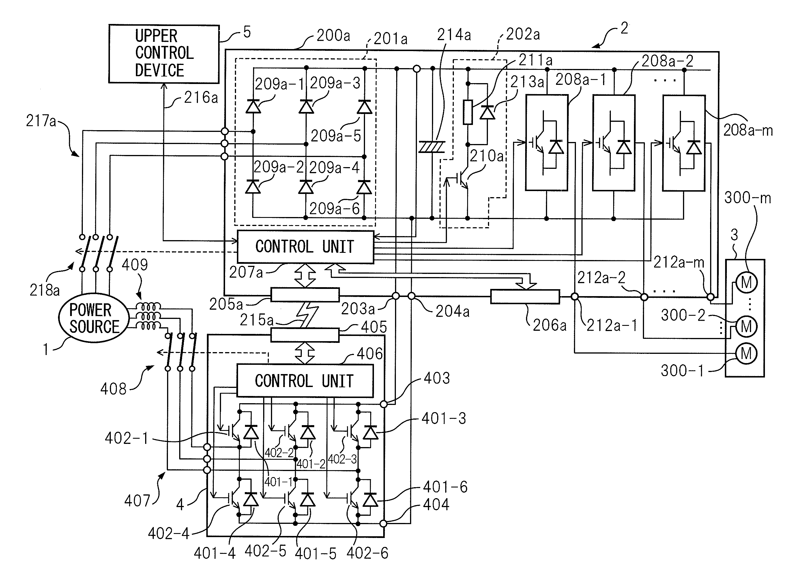
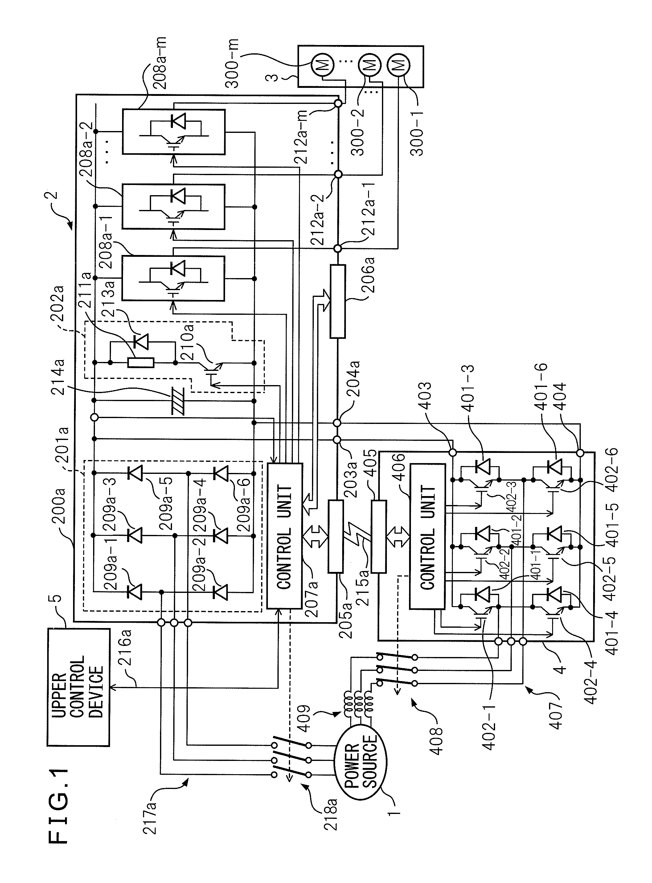
[0027]Referring to the drawings, FIG. 1 is a block diagram of a system having a servomotor drive device of the present invention. The system shown in FIG. 1 is used to drive a servomotor connected to a rotating shaft of a moving part of an industrial robot, and the system has a three-phase AC power source 1, a servomotor drive device 2, an industrial robot 3, a converter 4 as a second converter, and an upper control device 5.

[0028]In the present embodiment, the servomotor drive device 2 consists of one servomotor drive unit 200a. The servomotor drive unit 200a has a converter 201a as a first converter, a regenerative resistor circuit 202a, connectors 203a, 204a and multi-pin connectors 205a, 206a such as 8-pin connectors which constitute a first connection part (interface), and a control unit 207a.

[0029]The converter 201a has six diodes 209a-1, 209a-2, 209a-3, 209a-4, 209a-5, and 209a-6 bridge-connected as a plurality of first rectifier elements configured to supply DC power to the...

second embodiment

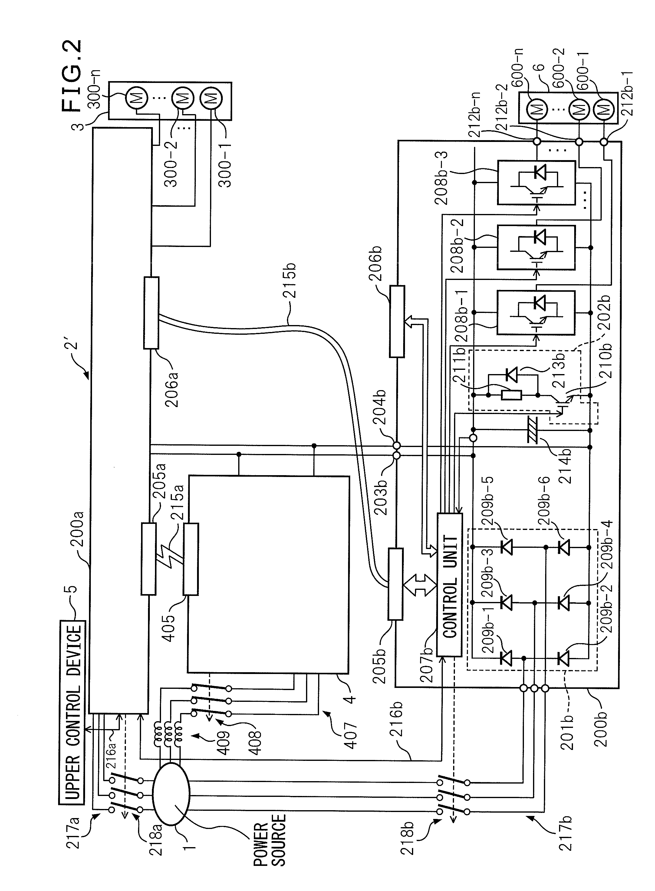
[0061]In the present embodiment, the servomotor drive device 2″ consists of two servomotors, that is, a servomotor drive unit 200a′ and the servomotor drive unit 200b. The servomotor drive unit 200b has the same configuration as that of the servomotor drive unit 200b of the second embodiment shown in FIG. 2, and therefore, explanation thereof is omitted and the components of the servomotor drive unit 200b are not shown in FIG. 3, except for the multi-pin connectors 205b, 206b.

[0062]The servomotor drive unit 200a′ has connectors 221a and 222a in addition to the converter 201a, the regenerative resistor circuit 202a, the connectors 203a and 204a, the multi-pin connectors 205a, 206a and the control unit 207a, and the connectors 221a, 222a constitute a second connection part (interface) together with a multi-pin connector 223a.

[0063]The connectors 221a, 222a are configured so that two pins (not shown schematically) provided on the DC current input side of an inverter unit 200c as a se...


PUM


Abstract

A servomotor drive device has a first converter, a regenerative resistor circuit having a first switching element and a regenerative resistor, a first connection part configured to connect a second converter in parallel to the regenerative resistor circuit in an attachable and detachable manner, and a first control unit configured to control the on and off states of the first switching element. The second converter has a second switching unit and a second control unit configured to return regenerative energy to an AC power source side by bringing the second switching element into the on state when the second converter is connected to the first connection part.

Description

BACKGROUND OF THE INVENTION[0001]1. Field of the Invention[0002]The present invention relates to a servomotor drive device to which the power source regeneration function to return regenerative energy generated during speed reduction of a servomotor connected to a rotating shaft of a moving part of an industrial robot to the AC power source side can be added, in accordance with operating conditions of the industrial robot.[0003]2. Description of Related Art[0004]Conventionally, in order to handle the regenerative energy generated during speed reduction of a servomotor, a servomotor drive device having a resistance regeneration function to consume the regenerative energy by a regenerative resistor and a servomotor drive device having the power source regeneration function to return the regenerative energy to the AC power source side are used.[0005]The servomotor drive device having the resistance regeneration function has a converter having a plurality of diodes configured to convert...

Claims


Application Information

Patent Timeline
Patent Type & Authority Applications(United States)
IPC IPC(8): H02P3/14H02P3/12B25J13/06H02P3/18H02P5/74H02P21/36H02P27/06
CPCH02P3/22H02P23/06H02P3/18
Inventor SUZUKI, NAOYUKIMATSUMOTO, YASUYUKI
Owner FANUC LTD
Why Eureka
Try Eureka