Unlock instant, AI-driven research and patent intelligence for your innovation.

Method or voltage detection system for determining a correction parameter for a measurement channel and for detecting a terminal voltage of an electric motor

Active Publication Date: 2013-05-09
ROBERT BOSCH GMBH
View PDF6 Cites 3 Cited by
  • Summary
  • Abstract
  • Description
  • Claims
  • Application Information

AI Technical Summary

Benefits of technology

The patent describes a device that measures the dynamic response of a channel and corrects for errors in the measurement. The device samples the output signal of the channel and measures the potential at the input of the channel. This information helps to accurately detect and correct for errors in the measurement. Additionally, the device can disconnect the connection terminal from the motor before measuring the potential to prevent any currents from flowing into the motor. The technical effects of this device include improved accuracy in measuring and correction, as well as preventing damage to the motor by reducing the likelihood of electrical arcing.

Problems solved by technology

However, the tapped off terminal voltage is corrupted by the measurement channel, as a result of which it is made more difficult to exactly determine the position and the rotation speed of the drive shaft of the electric motor.
However, the measurement channel also comprises non-linear elements, as a result of which exact detection of the terminal voltage is made more difficult.
In order to keep these non-linear deviations low, high-quality components are used, as a result of which the detection of the terminal voltage is associated with high costs.
Active components, for example operational amplifiers, are also sometimes used in order to be able to detect the terminal voltage with the desired degree of accuracy, this being associated with a great deal of effort and likewise high costs.

Method used


Image

  • Method or voltage detection system for determining a correction parameter for a measurement channel and for detecting a terminal voltage of an electric motor
  • Method or voltage detection system for determining a correction parameter for a measurement channel and for detecting a terminal voltage of an electric motor
  • Method or voltage detection system for determining a correction parameter for a measurement channel and for detecting a terminal voltage of an electric motor

Examples


Embodiment Construction

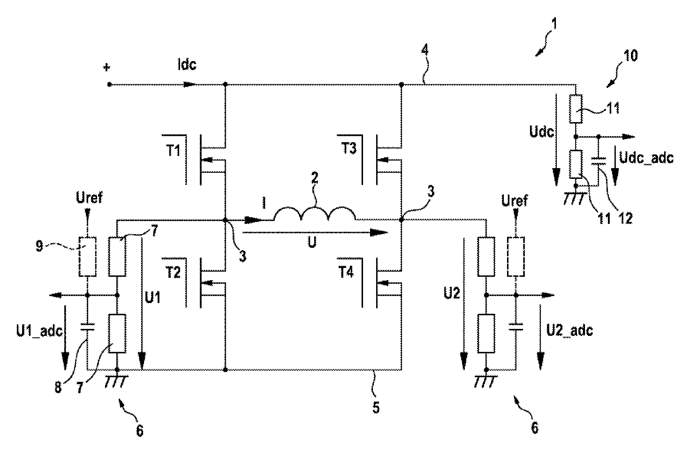
[0041]FIG. 1 shows a circuit arrangement 1 in which an electric motor 2 with two connection terminals 3 is arranged centrally. The current through the electric motor 2 is denoted I and the voltage dropped across said electric motor is denoted U. In this embodiment, the electric motor 2 is designed as a DC motor and is connected in an H-bridge circuit with a supply line 4 and an earth line 5. In this case, a first switching element in the form of a transistor T1, T3 is provided between each connection terminal 3 and the supply line 4, and a second switching element in the form of a transistor T2, T4 is provided between each connection terminal 3 and the earth line 5. The transistors T1, T2, T3, T4 are operated between the operating states “on” and “off” in the form of switches, wherein a control device (not shown) switches the transistors during operation.

[0042]Each connection terminal 3 is connected to a measurement channel 6. The measurement channel 6 which is connected to the conn...


PUM


Abstract

The invention relates to a method for determining a correction parameter for a measurement channel (6) which is connected to a connection terminal (3) of an electric motor (2) in order to measure a terminal voltage (U1, U2), characterized in that the connection terminal (3) is connected to a first potential via switching elements (T1, T2, T3, T4) for driving the electric motor (2), after a steady state of the measurement channel (6) has been reached, the connection terminal (3) is connected to a second potential, which differs from the first, by changing over at least one switching element (T1, T2, T3, T4), the dynamic response of the measurement channel (6) is detected following connection to the second potential, and the correction parameter for the dynamic response of the measurement channel (6) is determined on the basis of the detected dynamic response of the latter.

Description

BACKGROUND OF THE INVENTION[0001]The present invention relates to a general method for measuring a terminal voltage across a connection terminal of an electric motor.[0002]In the prior art terminal voltages, for example, of an electric motor are detected in order to be able to determine the rotation speed or else the exact position of the electric motor from said terminal voltages. By way of example, it is known in the case of DC motors or electrically commutated motors (EC motors) to detect the position and / or the rotation speed of the drive shaft of the electric motor without the use of a position sensor, which is fitted for example directly to the drive shaft, in a cost-effective manner. To this end, a voltage detection system is provided, said voltage detection system detecting one or more terminal voltages and transmitting said one or more terminal voltages to a control device in order to drive the electric motor. The voltage detection system can be designed as an integral cons...

Claims


Application Information

Patent Timeline
IPC IPC(8): G01R35/00
CPCG01R31/343G06Q10/00G01R19/00G01R31/34G01L1/00G01R1/00
Inventor FRICKER, DAVID
Owner ROBERT BOSCH GMBH