
System and Method for Automated Borescope Inspection User Interface

a technology of automated borescope inspection and user interface, applied in the field of automatic inspection techniques, can solve the problems of difficult classification of all kinds of blade damage defects within classes, easy errors in techniques, etc., and achieve the effect of improving automated defect detection

Active Publication Date: 2013-05-09
PRATT & WHITNEY +1
View PDF4 Cites 26 Cited by
  • Summary
  • Abstract
  • Description
  • Claims
  • Application Information

AI Technical Summary

Benefits of technology

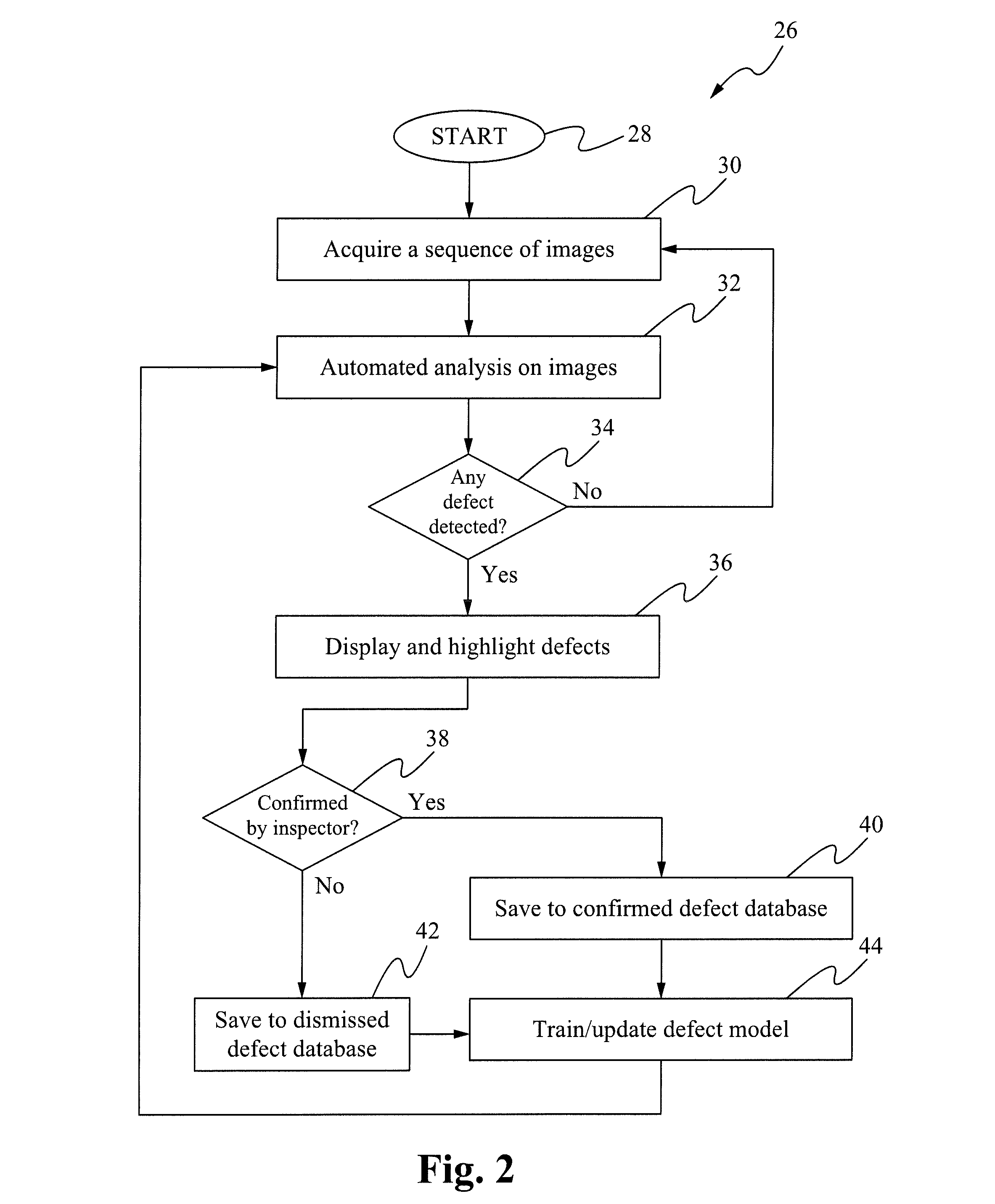
The patent is about a method to improve automated defect detection. It involves capturing and analyzing data of an object using an image capture device, and then reviewing the analysis results by a human inspector. The inspector then provides feedback to improve the accuracy of the automated analysis. This helps to detect defects in the object more effectively and efficiently.

Problems solved by technology

These techniques are prone to errors resulting from human inattention.
Although somewhat effective in circumventing errors from human involvement, categorizing all kinds of blade damage defects within classes is difficult and images having defects other than those pre-defined classes are not detected.

Method used


Image

  • System and Method for Automated Borescope Inspection User Interface
  • System and Method for Automated Borescope Inspection User Interface
  • System and Method for Automated Borescope Inspection User Interface

Examples


Embodiment Construction

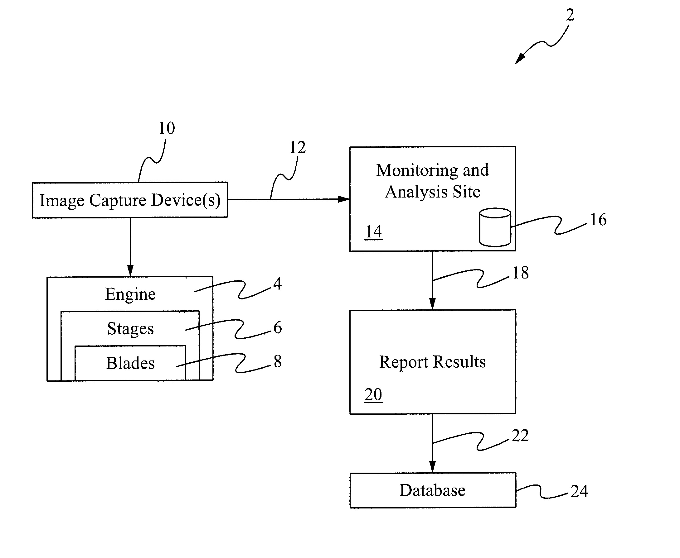
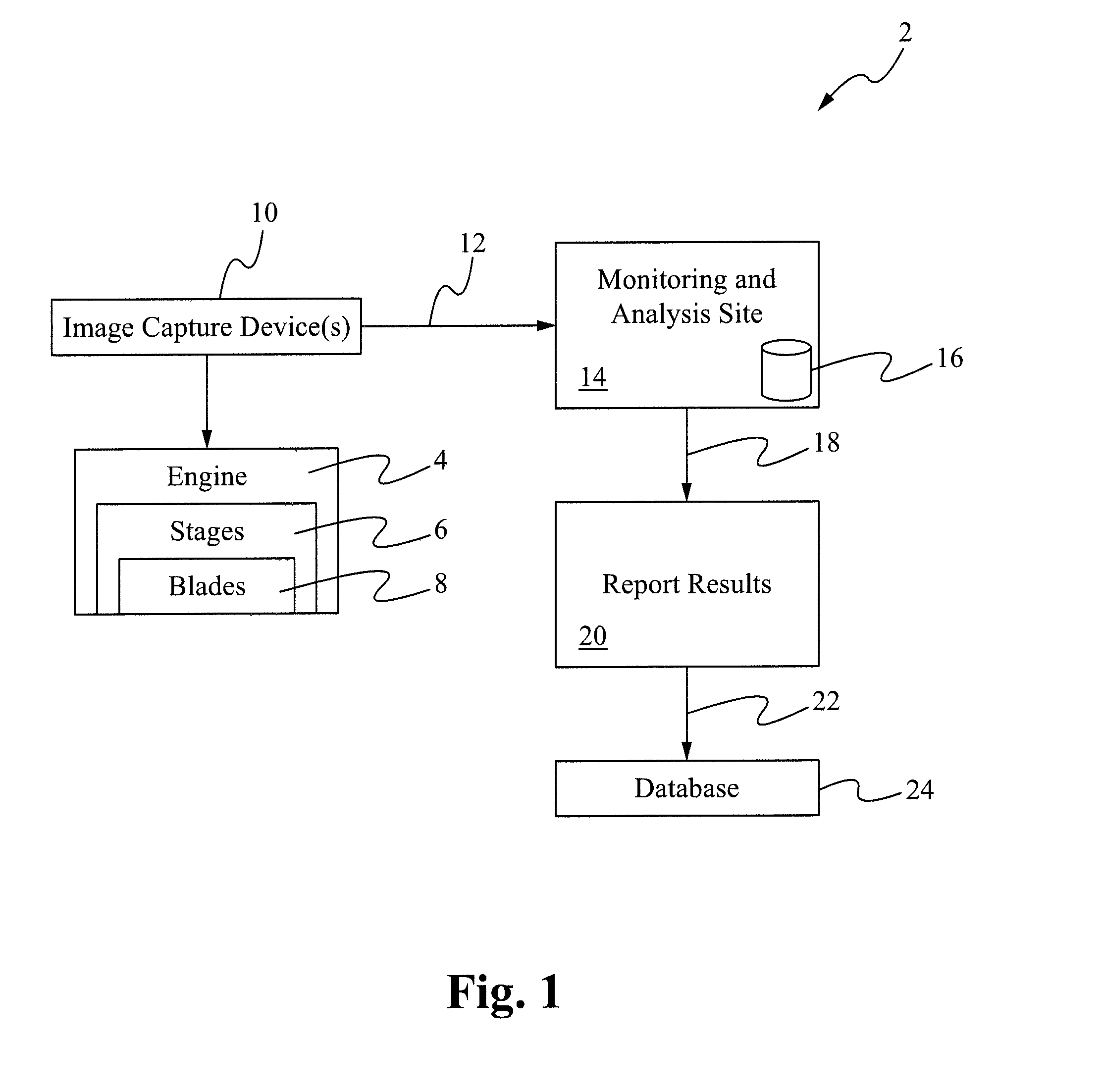
[0011]Referring to FIG. 1, a schematic illustration of an automated defect detection system 2 is shown, in accordance with at least some embodiments of the present disclosure. In at least some embodiments, the automated defect detection system 2 may be an automated borescope inspection (ABI) system. As shown, the automated defect detection system 2 may include an engine 4 having a plurality of stages 6, each of the stages having a plurality of blades 8, some or all of which may require visual inspection periodically at predetermined intervals, or based on other criteria by an image capture device 10. The engine may be representative of a wide variety of engines such as jet aircraft engines, aeroderivative industrial gas turbines, steam turbines, diesel engines, automotive and truck engines, and the like. Notwithstanding the fact that the present disclosure has been described in relation to visual inspection of the blades 8 of the engine 4, in other embodiments, the ABI system 2 may ...


PUM


Abstract

A system and method for improving human-machine interface while performing automated defect detection is disclosed. The system and method may include an image capture device for capturing and transmitting data of an object, performing automated analysis of the data and reviewing results of the automated analysis by a human inspector and providing feedback. The system and method may further include refining the automated analysis of the data based upon the feedback of the human inspector.

Description

TECHNICAL FIELD OF THE DISCLOSURE[0001]The present disclosure relates to automated inspection techniques and, more particularly, relates to automated visual inspection techniques of images or videos captured by image capture devices such as borescopes.BACKGROUND OF THE DISCLOSURE[0002]Video inspection systems, such as borescopes, have been widely used for capturing images or videos of difficult-to-reach locations by “snaking” image sensor(s) to these locations. Applications utilizing borescope inspections include aircraft engine blade inspection, power turbine blade inspection, internal inspection of mechanical devices and the like.[0003]A variety of techniques for inspecting the images or videos provided by borescopes for determining defects therein have been proposed in the past. Most such techniques capture and display images or videos to human inspectors for defect detection and interpretation. Human inspectors then decide whether any defect within those images or videos exists....

Claims


Application Information

Patent Timeline
Patent Type & Authority Applications(United States)
IPC IPC(8): H04N7/18
CPCG01N21/8851
Inventor SCHEID, PAUL RAYMONDGRANT, RICHARD C.FINN, ALAN MATTHEWWANG, HONGCHENGXIONG, ZIYOU
Owner PRATT & WHITNEY
Learn More