Eureka AIR delivers breakthrough ideas for toughest innovation challenges, trusted by R&D personnel around the world.

Geometric correction method and system for detecting lateral deviation of image of printed matter

A lateral offset and geometric correction technology, applied in image enhancement, image analysis, image communication, etc., can solve the problems of low mechanical oscillation frequency, image skew, inconsistent distortion degree of reference image and image to be inspected, etc. False detection rate, the effect of reducing differential artifacts

Active Publication Date: 2018-04-20
LANZHOU JIAOTONG UNIV
View PDF11 Cites 6 Cited by
  • Summary
  • Abstract
  • Description
  • Claims
  • Application Information

AI Technical Summary

Problems solved by technology

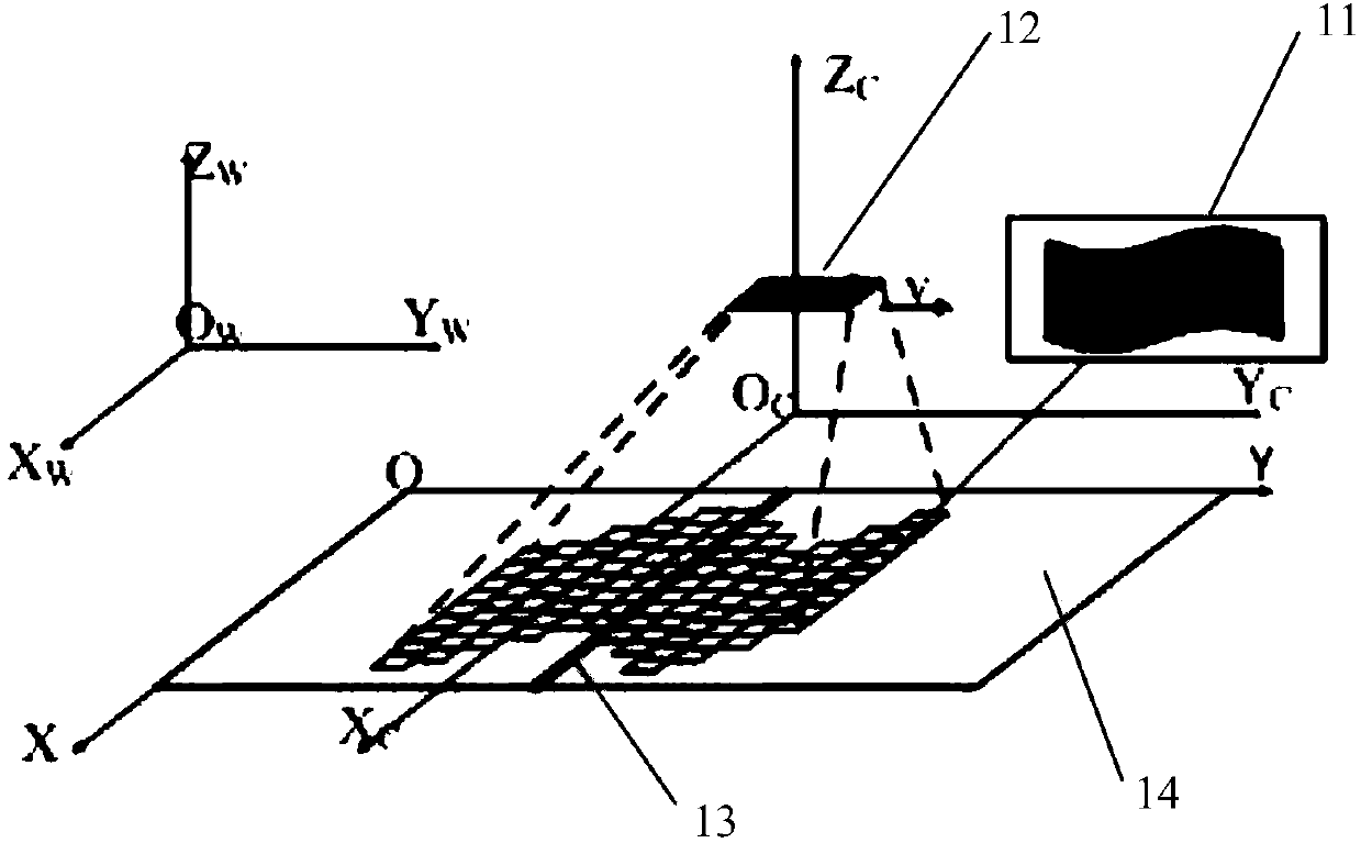
However, compared with the exposure frequency, the mechanical vibration frequency is relatively small, so the continuous exposure of the linear array CCD sensor 13 within an offset time period causes an image to be skewed, and a pair of distorted printed matter images can be obtained after multiple accumulations
[0006] In the subsequent defect detection, the degree of distortion and distortion of the reference image and the image to be inspected are inconsistent, which will lead to non-unique comparison variables between the two, which will cause great difficulties for real defect detection

Method used


Image

  • Geometric correction method and system for detecting lateral deviation of image of printed matter
  • Geometric correction method and system for detecting lateral deviation of image of printed matter
  • Geometric correction method and system for detecting lateral deviation of image of printed matter

Examples


Embodiment Construction

[0063] The following will clearly and completely describe the technical solutions in the embodiments of the present invention with reference to the accompanying drawings in the embodiments of the present invention. Obviously, the described embodiments are only some, not all, embodiments of the present invention. Based on the embodiments of the present invention, all other embodiments obtained by persons of ordinary skill in the art without making creative efforts belong to the protection scope of the present invention.

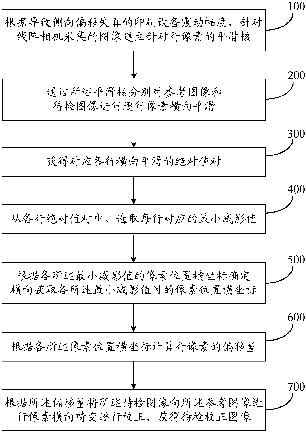
[0064] The purpose of the present invention is to provide a geometric correction method for the lateral offset of the printed matter detection image, by smoothing and checking the reference image and the image to be inspected to perform horizontal smoothing of pixels row by row, calculating the absolute value pairs in each row of smoothing, and selecting The minimum subtraction value, determining the abscissa of the pixel position when acquiring each of the min...


PUM


Abstract

The invention discloses a geometric correction method and system for detecting the lateral deviation of an image of a printed matter, and the method comprises the steps: building a smoothing kernel for row pixels of an image collected by a linear array camera according to the vibration amplitude, causing the distortion of the lateral deviation, of printing equipment; carrying out the lateral smoothing of the pixels of a reference image and a to-be-detected image row by row through the smoothing kernel; respectively calculating the absolute value pairs for the lateral smoothing of each row; selecting a minimum subtraction value, corresponding to each row, from the absolute value pairs of each row; determining the lateral coordinates of the pixel positions according to the lateral coordinates of the pixel positions of each minimum subtraction value during the obtaining of the minimum subtraction values; calculating the offset of the row pixels according to the lateral coordinates of thepixel positions so as to correct the lateral distortion of the pixels of the to-be-detected image to the reference image, thereby facilitating the subsequent detection of the defects of the printed matter through the to-be-detected image, guaranteeing the comparison premise of a single variable of two images, reducing the differential artifact greatly, and reducing the defect detection error rate.

Description

technical field [0001] The invention relates to the technical field of printed matter detection image detection, in particular to a geometric correction method and system for lateral offset of printed matter detection images. Background technique [0002] In the print image defect detection module, the inconsistency between the product to be inspected and the qualified product is found by comparing the image of the qualified product (also called the reference image) with the image of the product to be inspected (also called the image to be inspected), which is defined as a defect. During the shooting process of the printed product image, the actual shooting environment of the qualified product and the product to be inspected is not absolutely consistent, and distortion such as lateral distortion may occur. Therefore, the printed product to be inspected must be back-corrected to the qualified product image before defect detection, so The images of qualified products and untes...

Claims


Application Information

Patent Timeline
Patent Type & Authority Applications(China)
IPC IPC(8): H04N5/14G06T5/00G06T7/00G01N21/956
CPCH04N5/14G06T7/001G01N21/956G06T2207/30144G06T5/80G06T5/70
Inventor 王阳萍党建武徐绍伟王松杨景玉杜晓刚闵永智张振海王文润雍玖
Owner LANZHOU JIAOTONG UNIV
Why Eureka
Eureka Blog
Learn More