Method and apparatus for transmitting uplink data in a wireless access system

a wireless access system and data transmission technology, applied in the field of wireless access systems, can solve the problems of inability to apply conventional data transmission, inability to reduce the overhead of lower performance or capability of m2m devices used in a cellular network. the effect of avoiding unnecessary resources and reducing control overhead in a higher layer

Inactive Publication Date: 2013-05-09
LG ELECTRONICS INC
View PDF4 Cites 89 Cited by
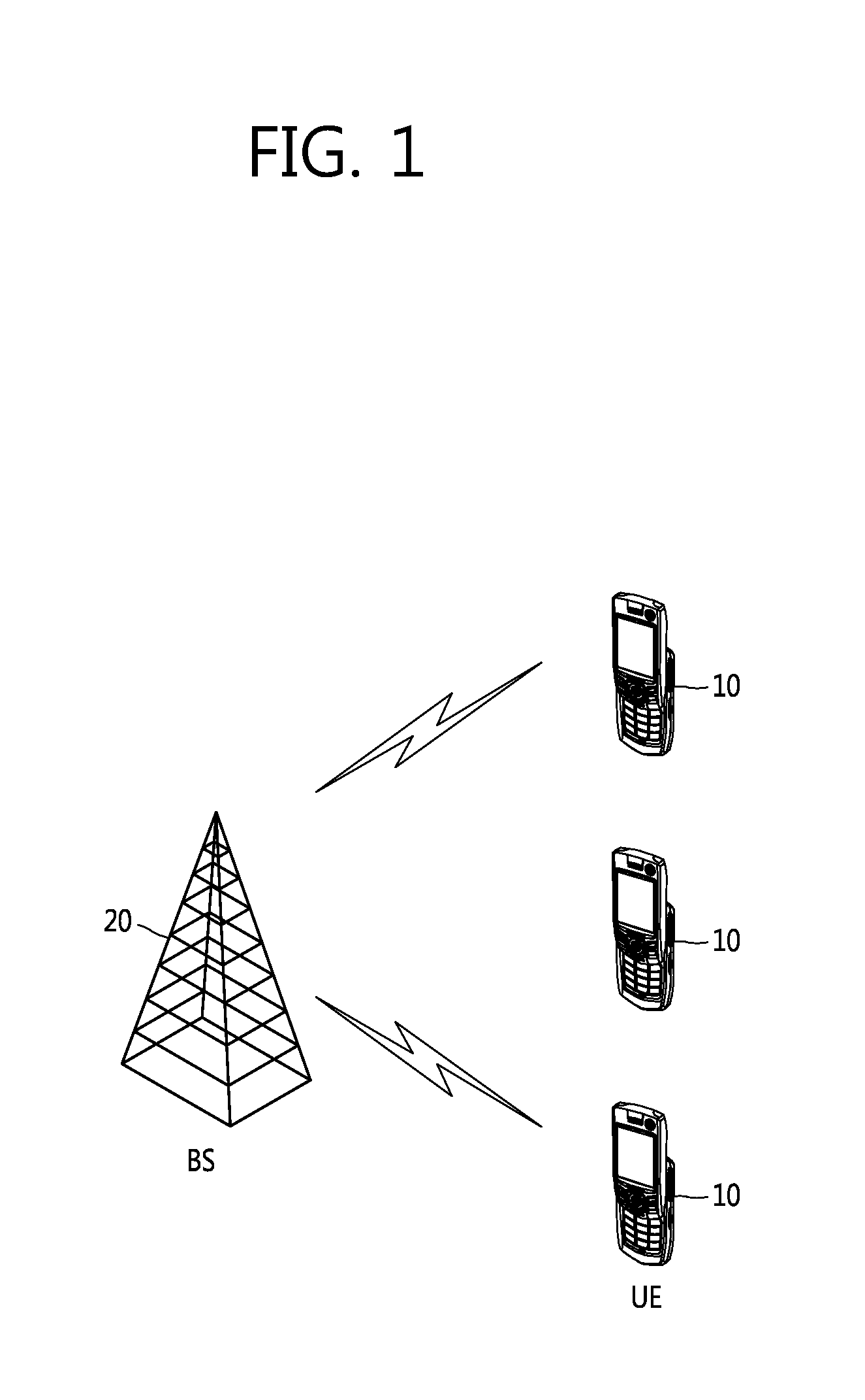
  • Summary
  • Abstract
  • Description
  • Claims
  • Application Information

AI Technical Summary

Benefits of technology

[0019]The present invention provides a method for effectively supporting a great number of machine type communication (MTC) user equipments (UEs) which generate a small data burst.
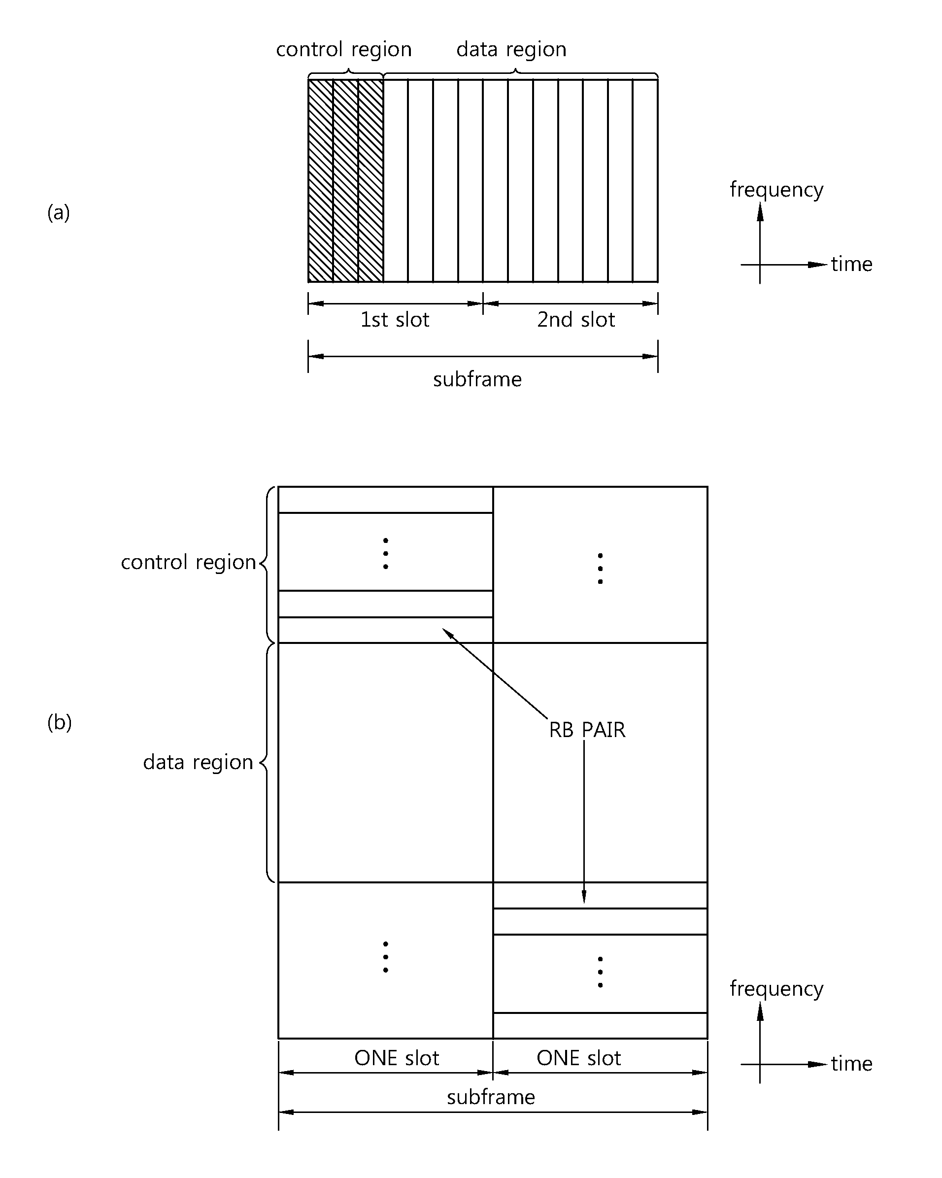
[0020]In particular, the present invention provides a method for effectively transmitting a small data burst in accordance with a structure of a long term evolution (LTE) / LTE-advanced (LTE-A) physical / logical resource block or an 802.16 physical / logical resource unit currently used as a basic unit of data scheduling, and a scheduling method thereof.
[0021]That is, the present invention provides a method in which scheduling is performed effectively by grouping MTC UEs which report small data to a base station according to the same data transmission period, and data is transmitted by effectively multiplexing within the existing PRB in such a manner that an amount of resource elements (REs) necessary in transmission is minimized by decreasing an overhead of a higher layer.
[0047]According to the present invention, to transmit small data, a plurality of machine type communication (MTC) user equipments (UEs) are multiplexed in a code division multiplexing (CDM) manner and transmit uplink data through the same region. Therefore, waste of unnecessary resources can be avoided, and a control overhead in a higher layer can be decreased.

Problems solved by technology

Furthermore, M2M devices used in a cellular network have lower performance or capability than common terminals.
As such, in a case where a great number of MTC UEs employed by the same user or service provider generate a small amount of data having the same feature and transmit the data to a base station according to the same period, the conventional resource allocation method used for this is disadvantageous not only in terms of a control channel overhead for scheduling information transmission but also in a sense that a control overhead (e.g., MAC header) or the like in a MAC layer applied for the conventional data transmission can be significantly increased in comparison with an actual information bit size.
In addition, it may be inappropriate to apply the conventional channel coding scheme to perform small data transmission, and it may also be inappropriate to apply a size of a CRC attached to apply HARQ, a physical resource block size used as the conventional resource allocation unit, etc.

Method used


Image

  • Method and apparatus for transmitting uplink data in a wireless access system
  • Method and apparatus for transmitting uplink data in a wireless access system
  • Method and apparatus for transmitting uplink data in a wireless access system

Examples


first embodiment

[0115]The first embodiment provides a method in which a plurality of MTC UEs transmits

[0116]UL data in a CDM manner according to an embodiment of the present invention.

[0117]FIG. 6 is a flowchart showing a UL data transmission method of an MTC UE according to a first embodiment of the present invention.

[0118]Referring to FIG. 6, the MTC UE receives UL resource allocation information (i.e., a UL grant) for UL data transmission from a BS through a DL control channel (step S610). Herein, the UL resource allocation information includes at least resource block allocation information regarding a resource block allocated to each slot constituting the subframe and modulation and coding scheme (MCS) information. Herein, the resource block allocation information and the MCS information may be transmitted semi-statically through higher-layer signaling.

[0119]Thereafter, the MTC UE receives sequence information regarding a sequence allocated for each UE from the BS to transmit UL data in a CDM m...

second embodiment

[0160]The second embodiment provides an HARQ ACK / NACK feedback method for a plurality of MTC devices which transmit UL data on the basis of CDM according to an embodiment of the present invention.

[0161]FIG. 7 is a flowchart showing an HARQ ACK / NACK feedback method according to a second embodiment of the present invention.

[0162]Since step S710 to step S740 are identical to step S610 to step S640 of FIG. 6, descriptions thereof are omitted, and only a different step, i.e., S750, will be described.

[0163]After step S740, the BS transmits an HARQ response on UL data received from the MTC UE, to the MTC UE through a PHICH (step S750). Herein, the HARQ response refers to HARQ ACK or NACK.

[0164]Hereinafter, a resource mapping method for a PHICH on which the HARQ response is transmitted will be described.

[0165]First, a PHICH in a 3GPP LTE / LTE-A system will be described in brief.

[0166]The PHICH is a channel for transmitting ACK / NACK information for a UL data channel. Several PHICH groups can ...

third embodiment

[0191]The third embodiment provides a UL data retransmission method when an MTC UE receives HARQ NACK for UL data from a BS according to an embodiment of the present invention.

[0192]FIG. 8 is a flowchart showing a UL data retransmission method of an MTC UE according to a third embodiment of the present invention.

[0193]Since step S810 to step S850 are identical to step S710 to step S750 of FIG. 7, descriptions thereof are omitted, and only a different step, i.e., S860, will be described.

[0194]After step S850, the MTC UE performs a retransmission process for UL data (i.e., PUSCH) (step S860). Herein, the MTC UE can perform the retransmission process by using a synchronous non-adaptive scheme or a synchronous adaptive scheme.

[0195]First, in a process of performing retransmission on corresponding PUSCH transmission by using the synchronous non-adaptive scheme, initial UL data transmission may be achieved by multiplexing 12 MTC UEs through CDM in given one RB pair. In this case, if a dec...


PUM


Abstract

The present description relates to a method for a terminal to transmit uplink (UL) data in a wireless access system, comprising the following steps: receiving uplink resource allocation information for uplink data transmission from a base station via a downlink control channel, wherein the uplink resource allocation information includes resource block allocation information for each slot of a subframe and modulation and coding scheme (MCS) information; receiving, from the base station, sequence information allocated to each terminal so as to transmit uplink data through a code division multiplexing (CDM) scheme in cooperation with other terminals in a resource block pair region of the subframe; and transmitting uplink data to the base station through the resource block pair region in accordance with the received sequence information.

Description

BACKGROUND OF THE INVENTION[0001]1. Field of the Invention[0002]The present invention relates to a wireless access system, and more particularly, to a method and apparatus for transmitting uplink data.[0003]2. Related Art[0004]A machine-to-machine (M2M) communication (machine type communication, MTC) is described in brief below.[0005]Machine to machine (M2M) communication as it is means communication between electronic devices. That is, M2M communication means communication between things. In general, M2M communication means wired or wireless communication between electronic devices or communication between a device and a machine which are controlled by human beings, but M2M communication is used to specially denote wireless communication between an electronic device and an electronic device, that is, devices. Furthermore, M2M devices used in a cellular network have lower performance or capability than common terminals.[0006]There are many terminals within a cell, and the terminals ...

Claims


Application Information

Patent Timeline
Patent Type & Authority Applications(United States)
IPC IPC(8): H04W72/04
CPCH04L5/0053H04L5/0094H04W72/0466H04W72/0446H04W72/042H04W4/70H04W72/23H04B1/713H04L1/1864H04W72/21
Inventor PARK, KYUJINKIM, DONGCHEOLCHO, HANGYULIM, DONGGUK
Owner LG ELECTRONICS INC
Why Eureka
Try Eureka