
Acoustic wave measuring apparatus and control method of acoustic wave measuring apparatus

a technology of acoustic wave and measuring apparatus, which is applied in the direction of ultrasonic/sonic/infrasonic device control, medical science, diagnostics, etc., can solve the problems of increasing the burden of response, the measurement of objects is much time-consuming, and the movement distance is increased, so as to simplify the setting operation

Inactive Publication Date: 2013-05-09
CANON KK
View PDF5 Cites 21 Cited by
  • Summary
  • Abstract
  • Description
  • Claims
  • Application Information

AI Technical Summary

Benefits of technology

The present invention is an acoustic wave measuring apparatus that aims to simplify the setup for users and determine a scanning path for multiple regions of interest based on priority. The apparatus determines a scanning order for stripes with the same priority to minimize the movement distance of the acoustic probe. This results in a more efficient and user-friendly acoustic wave measuring experience.

Problems solved by technology

A conventional measuring apparatus has a problem in that much time is required for measuring an object in both photoacoustic measurement and ultrasound measurement.
In fact, the level of burden felt in response to the compression and fixation will vary among different individuals, and certain subjects are unable to withstand such compression and fixation for a long period of time.
Nevertheless, when there are a plurality of set regions of interest, the acoustic probe makes a round by scanning all regions and, therefore, the movement distance increases, and there is a problem in that wasted time results depending on the scanning order.
Nevertheless, for a conventional apparatus to deal with the foregoing problem, the user was required to personally be aware of the foregoing circumstances and designate the scanning track in order from the location of highest priority, and the operation was complicated.

Method used


Image

  • Acoustic wave measuring apparatus and control method of acoustic wave measuring apparatus
  • Acoustic wave measuring apparatus and control method of acoustic wave measuring apparatus
  • Acoustic wave measuring apparatus and control method of acoustic wave measuring apparatus

Examples


first embodiment

[0072]The operation of the photoacoustic measuring apparatus according to the first embodiment is now explained in detail with reference to the drawings.

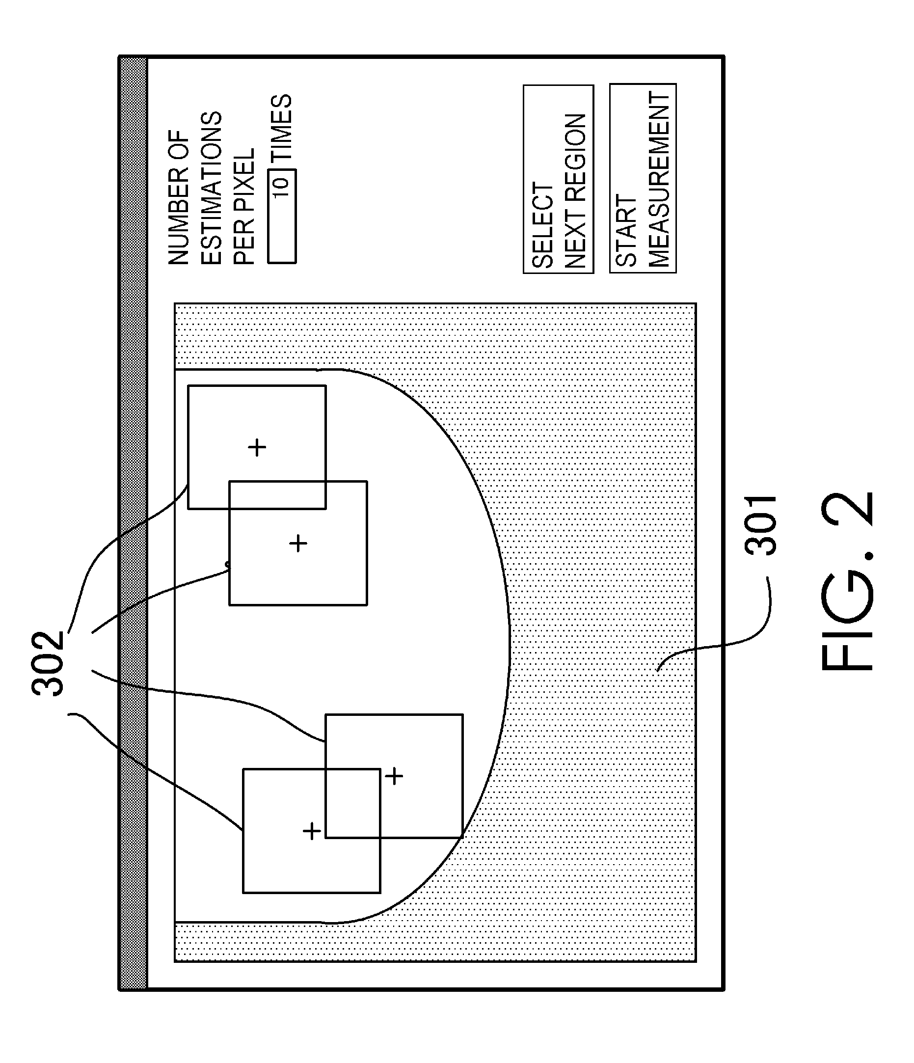
[0073]A plurality of measurement designated regions, so called regions of interest, are designated by a user via the region designating unit 201. A specific example of the designation of the measurement designated region by the user is shown in FIG. 4. In the diagram, 406 represents a region corresponding to the observed image, and is a planar range in which the acoustic probe can perform scanning. 401 to 405 are measurement designated regions that were designated by the user. 401 to 403 are regions which are set with a high priority (let this be priority 1), and 404, 405 are regions which are set with a low priority (let this be priority 2). As shown in the diagram, regardless of the setting of priority, it is also possible to designate the measurement designated regions in a mutually overlapping state. The designated regions of in...

second embodiment

[0114]The second embodiment is the mode of detecting a portion which overlaps with the regions of different priorities and optimizing the shape of the regions in step (S4) of dividing the scanning region shown in the first embodiment. The processing other than step S4 and the system configuration are the same as the first embodiment.

[0115]FIG. 9 is a diagram showing the state of data accumulation of the region that was captured while moving the acoustic probe. In the diagram, the observer's right-side direction is the main scanning direction. The checkered rectangle represents the location where the receiving elements of the acoustic probe existed upon performing photoacoustic measurement while shifting the acoustic probe in the main scanning direction one element at a time. In order to perform photoacoustic measurement while shifting the acoustic probe in the main scanning direction one element at a time, the scanning region will be, as shown in the diagram, filled by grids of the ...

third embodiment

[0124]The third embodiment is a mode of changing the assignment method in step (S3) of assigning the stripes to the inclusion region. Upon assigning the stripes to the inclusion region, the stripe arrangement position is adjusted so that measurement of regions of all priorities is completed with the shortest possible scanning distance. Note that the processing other than step S3 and the system configuration are the same as the second embodiment.

[0125]With the photoacoustic measuring apparatus according to the first and second embodiments, since the photoacoustic measurement is performed in stripe units, excess regions will be measured when they are smaller than the height of the actual scanning regions in which the measurement designated regions designated by the user. If it is possible to measure the measurement designated region, the excess regions may be located anywhere, and the stripes may be moved in the sub scanning direction in the amount of the width of the excess region.

[0...


PUM


Abstract

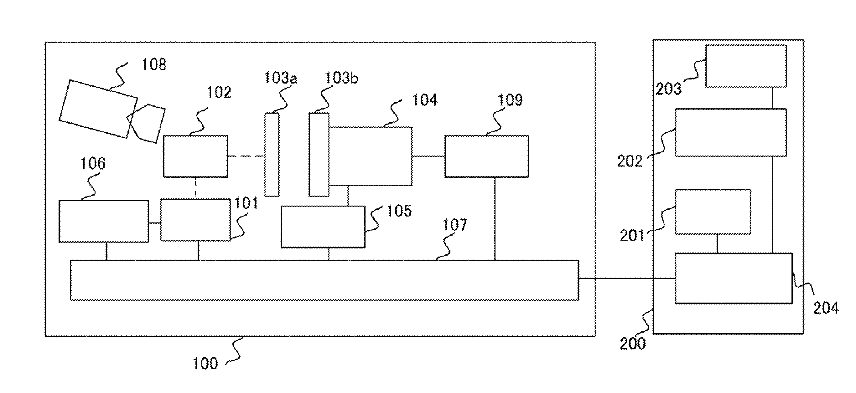
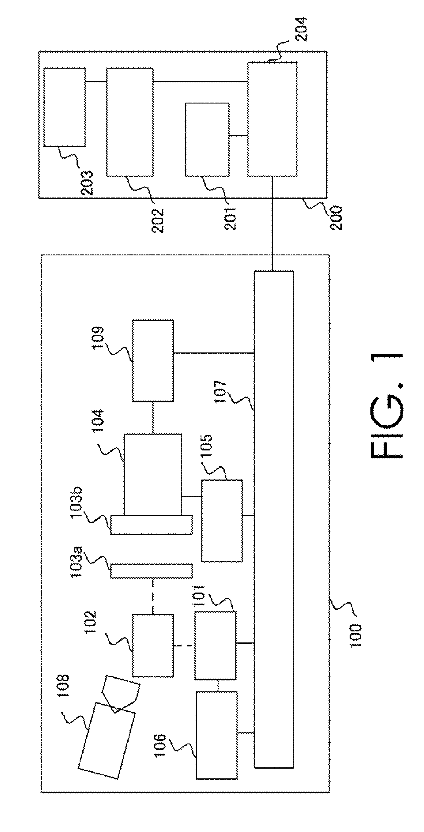
Provided is an acoustic wave measuring apparatus including: an acoustic probe; region-of-interest setting unit for setting two or more regions of interest for an object; priority setting unit for setting priorities on the regions of interest; region calculating unit for determining, for each of the set priorities, an inclusion region including the regions of interest set with the priority; scanning method determining unit for assigning a scanning stripe to each of the inclusion regions so as to include all regions of interest included in the inclusion region; scanning path identifying unit for determining a scanning order of a plurality of scanning stripes having a same priority so as to shorten a movement distance of the acoustic probe; and scanning unit for scanning the scanning stripes according to the determined scanning order, based on the priority order, by moving the acoustic probe.

Description

BACKGROUND OF THE INVENTION[0001]1. Field of the Invention[0002]The present invention relates to an acoustic wave measuring apparatus and a control method of such an acoustic wave measuring apparatus.[0003]2. Description of the Related Art[0004]An ultrasound measuring apparatus of imaging the structure inside a biological object by transmitting ultrasound waves to the biological object and analyzing the reflected ultrasound waves has been put into practical application in the medical area. When ultrasound waves are transmitted to the biological object, the reflection of ultrasound waves occurs at the interfaces in the biological object having different acoustic impedances. An ultrasound measuring apparatus images configuration information in the biological object by analyzing the reflected waves and detecting the interfaces.[0005]Moreover, in recent years, technology has been devised for analyzing the structure and condition of the surface and inside of a biological object by irradi...

Claims


Application Information

Patent Timeline
Patent Type & Authority Applications(United States)
IPC IPC(8): A61B6/00
CPCA61B8/5292A61B8/469A61B5/0095A61B8/54
Inventor SATO, AKIRA
Owner CANON KK
Learn More