Modular modeling and design of antennas and radio frequency circuits that are arranged in a class of composite structural configurations

a radio frequency circuit and module technology, applied in computing, instruments, electric digital data processing, etc., can solve the problems of limited practical use, inapplicability of simple and efficient planar models currently available, and computational complexity and cost of general brute force solutions (e.g., using maxwell's equations). achieve the effect of computational efficiency

Inactive Publication Date: 2013-05-09
POLYTECHNIC INSTITUTE OF NEW YORK UNIVERSITY
View PDF26 Cites 9 Cited by
  • Summary
  • Abstract
  • Description
  • Claims
  • Application Information

AI Technical Summary

Benefits of technology

[0008]The problem of modeling and designing a structure including (1) one or more planar elements (e.g., a planar antenna, a planar RF circuit, etc.) arranged in association with (2) one or more non-planar elements (e.g., a non-planar packaging, a non-planar scattering element, a complex meta material, a periodic array element, etc.), in a computationally efficient and rigorous manner, is solved by (1) modeling each of the one or more planar elements using both (i) conventional space-spectral analysis and (ii) complex space-spectral analysis to obtain an electro-magnetic (EM) signature matrix for each of the one or more planar elements, (2) determining (e.g., using a brute force modeling based on Maxwell's equations, by measuring experimentally, or by reading one from a stored library) an EM signature matrix (e.g., reflection and scattering matrices) compatible with those of the planar elements, for each of the one or more non-planar elements, and (3) combining the EM signatures of each of the one or more planar elements and the EM signatures of each of the one or more non-planar elements using matrix analysis to obtain a complete EM signature of the structure, from which any specific input / output characteristics of the system can be obtained as needed.

Problems solved by technology

As discussed above, general brute-force solutions (e.g., using Maxwells' equations) can become so computationally complex and expensive, that they are of limited practical (or no) use when it is desired to incorporate design rearrangements or incremental iterative design changes.
Unfortunately, such simple and efficient planar models currently available are not applicable to structures that include general non-planar structures or a meta-material environment.
However, this can be time consuming and potentially inaccurate, particularly when a large number of singularities are included.

Method used


Image

  • Modular modeling and design of antennas and radio frequency circuits that are arranged in a class of composite structural configurations
  • Modular modeling and design of antennas and radio frequency circuits that are arranged in a class of composite structural configurations
  • Modular modeling and design of antennas and radio frequency circuits that are arranged in a class of composite structural configurations

Examples


Embodiment Construction

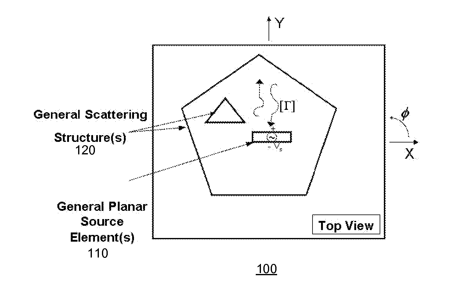
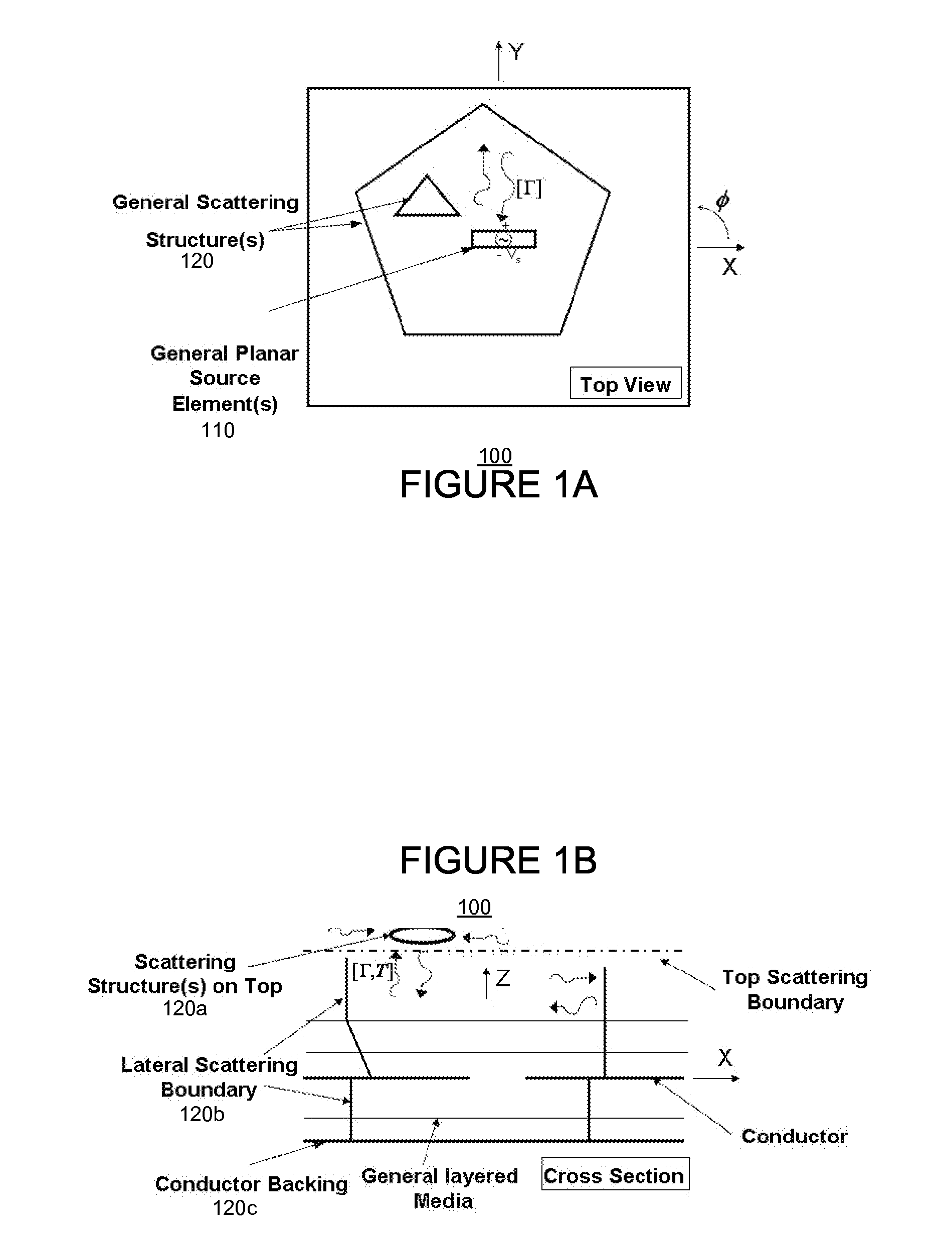
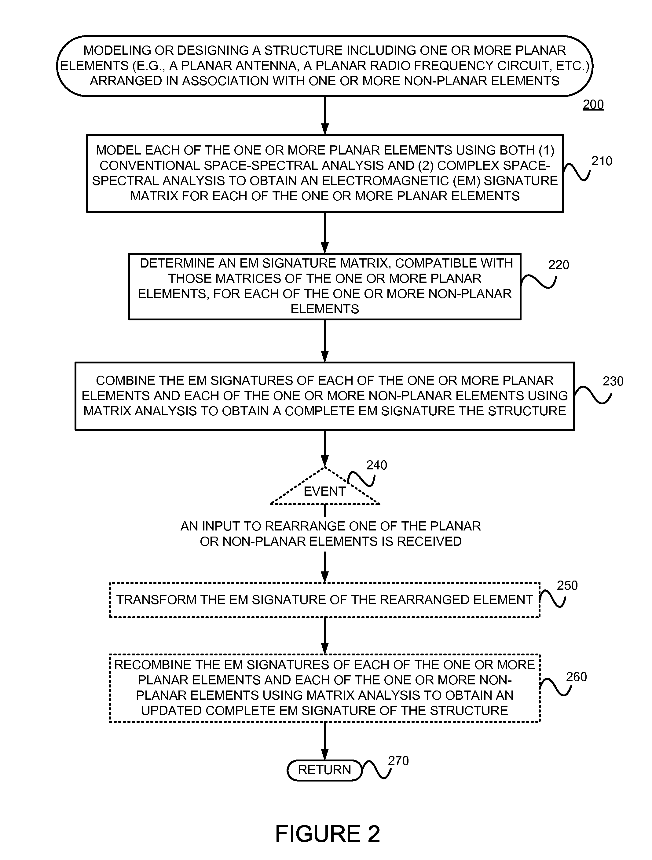
[0021]The present invention may involve novel methods, apparatus, message formats, and / or data structures for modeling and design of devices that emit or receive electro-magnetic (EM) radiation, such as antennas and radio-frequency (RF) circuits. The following description is presented to enable one skilled in the art to make and use the invention, and is provided in the context of particular applications and their requirements. Thus, the following description of embodiments consistent with the present invention provides illustration and description, but is not intended to be exhaustive or to limit the present invention to the precise form disclosed. Various modifications to the disclosed embodiments will be apparent to those skilled in the art, and the general principles set forth below may be applied to other embodiments and applications. For example, although a series of acts may be described with reference to a flow diagram, the order of acts may differ in other implementations w...


PUM


Abstract

The problem of modeling and designing a structure including a planar element(s) (e.g., antenna, RF circuit, etc.) arranged in association with a non-planar element(s) (e.g., non-planar packaging, a non-planar scattering element, a complex meta material, a periodic array element, etc.), in a computationally efficient and rigorous manner is solved by (1) modeling each of the planar elements using both conventional space-spectral analysis and complex space-spectral analysis to obtain an electro-magnetic (EM) signature matrix for each planar element, (2) determining (e.g., using a brute force modeling based on Maxwell's equations, by measuring experimentally, or by reading one from a stored library) an EM signature matrix (e.g., reflection and scattering matrices) compatible with those of the planar elements, for each of the non-planar elements, and (3) combining the EM signatures of the elements using matrix analysis to obtain a complete EM signature the structure.

Description

§1. RELATED APPLICATIONS[0001]This application claims the benefit of U.S. Provisional Patent Application Ser. No. 61 / 504,006 (incorporated herein by reference and referred to as the “006 provisional”), filed on Jul. 1, 2011, titled “A NEW EFFICIENT AND VERSATILE COMPUTER TECHNIQUE FOR MODULAR MODELING AND DESIGN OF ANTENNAS AND RADIO-FREQUENCY CIRCUITS, THAT ARE ARRANGED IN A CLASS OF COMPOSITE STRUCTURAL CONFIGURATIONS ( . . . , INCLUDING PLANAR ELEMENTS EMBEDDED IN A GENERAL NON-PLANAR PACKAGING / SCATTERING ENVIRONMENT, A METAMATERIAL MEDIUM, OR A PERIODIC ARRAY ENVIRONMENT, ALLOWING FLEXIBLE REARRANGEMENT OR MODIFICATION OF PARTS OF DIFFERENT SHAPE, SIZE AND FUNCTIONALITY, AND INDEPENDENT HIERARCHICAL DESIGN OF EACH PART USING DIFFERENT TECHNIQUE OR ACCURACY)” and listing Nirod DAS as the inventor. The present invention is not limited to requirements of the particular embodiments described in the '006 provisional application.§2. BACKGROUND OF THE INVENTION[0002]§2.1 Field of the I...

Claims


Application Information

Patent Timeline
Patent Type & Authority Applications(United States)
IPC IPC(8): G06F17/50
CPCG06F17/5036G06F17/50G06F30/367G06F30/00
Inventor DAS, NIROD K.MCCABE, BRIAN
Owner POLYTECHNIC INSTITUTE OF NEW YORK UNIVERSITY
Why Eureka
Try Eureka