
Module for a thermal absorber of a solar receiver, absorber comprising at least one such module and receiver comprising at least one such absorber

a technology of solar receiver and module, which is applied in the direction of solar heat collector for particular environment, solar heat collector with working fluid, etc., can solve the problems of sudden increase in the temperature of the tube wall, insufficient efficiency of the receiver, and heat damage to the selective surface treatmen

Inactive Publication Date: 2013-05-16
COMMISSARIAT A LENERGIE ATOMIQUE ET AUX ENERGIES ALTERNATIVES
View PDF10 Cites 13 Cited by
  • Summary
  • Abstract
  • Description
  • Claims
  • Application Information

AI Technical Summary

Benefits of technology

The present invention is a module for the production of an absorber for a solar receiver of a thermal power plant. The module has a single channel for the flow of a pressurized heat transfer fluid and is designed to keep the absorber pressurized. The module also includes means for reblending the fluid, homogenizing the temperature, and preventing the appearance of hot points. The absorber is a heat exchanger with a single duct that is suitable for a flow of concentrated solar energy flux on a single one of its faces. The absorber is coated with a material that improves its absorption of the sun's energy and has low infrared emissivity properties. The technical effects of the invention are the improved collection and utilization of solar energy, reduced thermal degradation of the absorber and surface coating, and increased efficiency of the thermal power plant.

Problems solved by technology

But this selective surface treatment can be heat damaged; it is therefore important to prevent the appearance of hot points.
In addition, the zones located between the tubes which also receive the concentrated solar flux are not used to heat the fluid, and the efficiency of the receiver is therefore not optimal.
In addition, in the zones of the absorber where the solar flux is potentially very concentrated, for example due to a mirror focusing error, the temperature of the wall of the tube increases suddenly and the selective surface treatment applied to the tube may be damaged rapidly, and there may therefore be a drop in performance of the solar receiver.

Method used


Image

  • Module for a thermal absorber of a solar receiver, absorber comprising at least one such module and receiver comprising at least one such absorber
  • Module for a thermal absorber of a solar receiver, absorber comprising at least one such module and receiver comprising at least one such absorber
  • Module for a thermal absorber of a solar receiver, absorber comprising at least one such module and receiver comprising at least one such absorber

Examples


Embodiment Construction

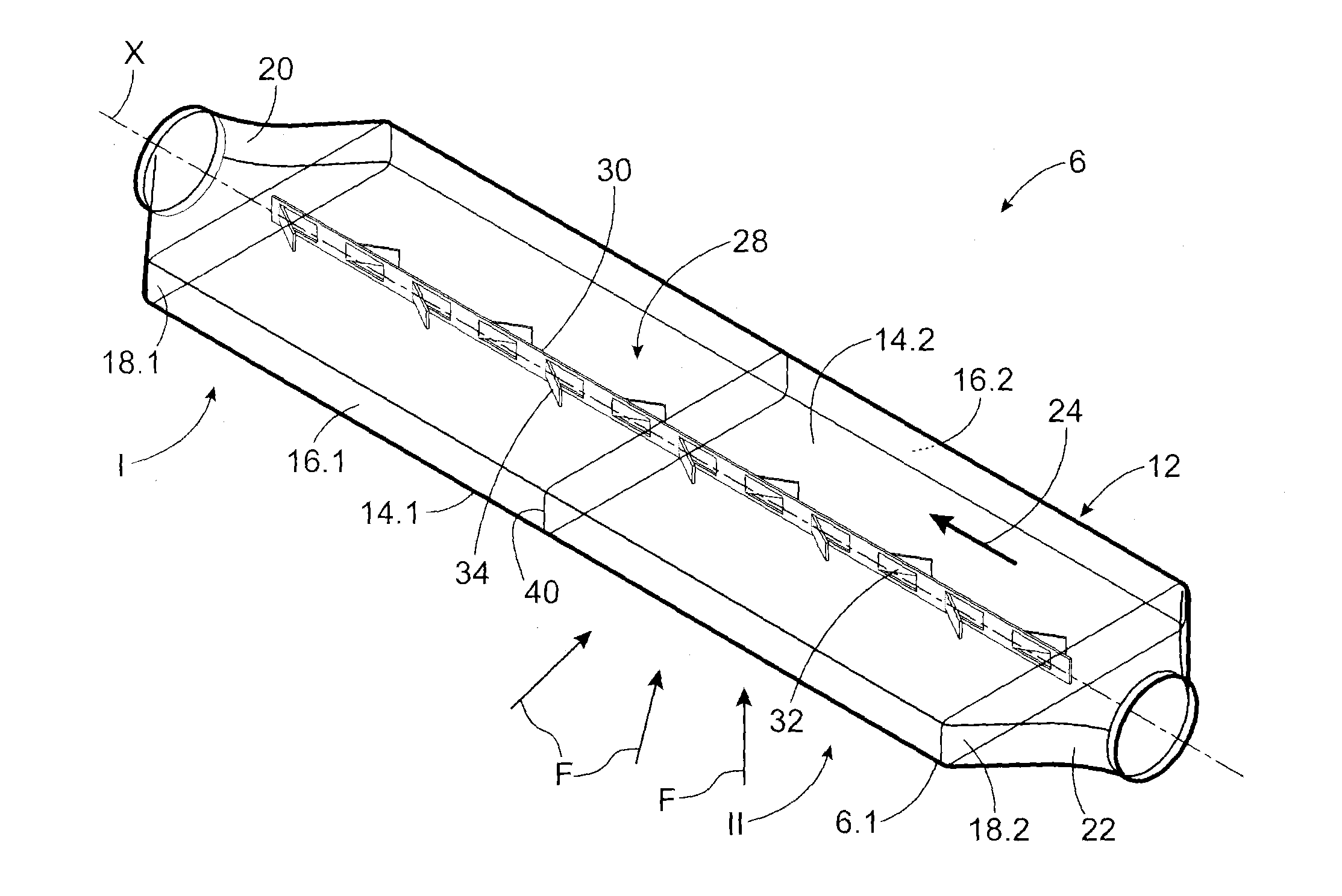
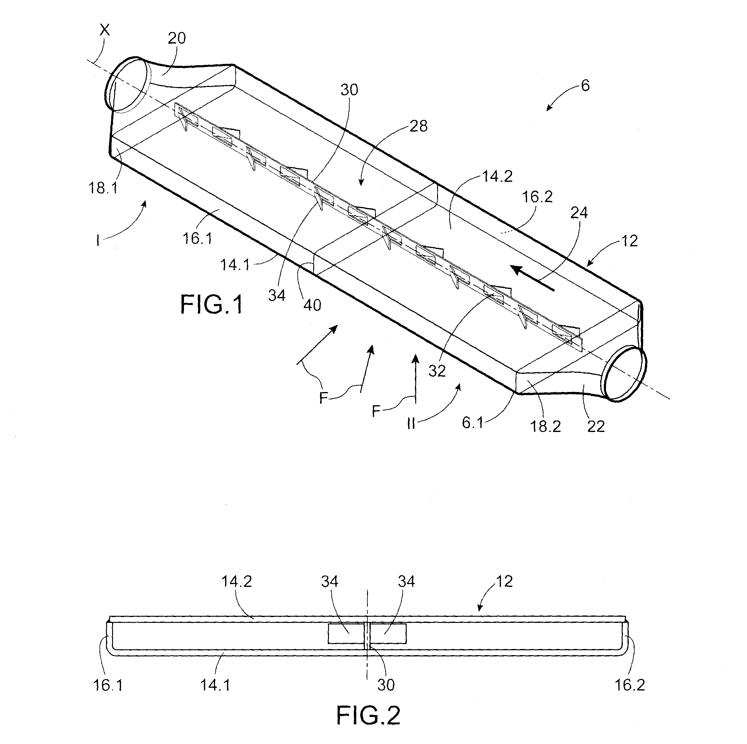
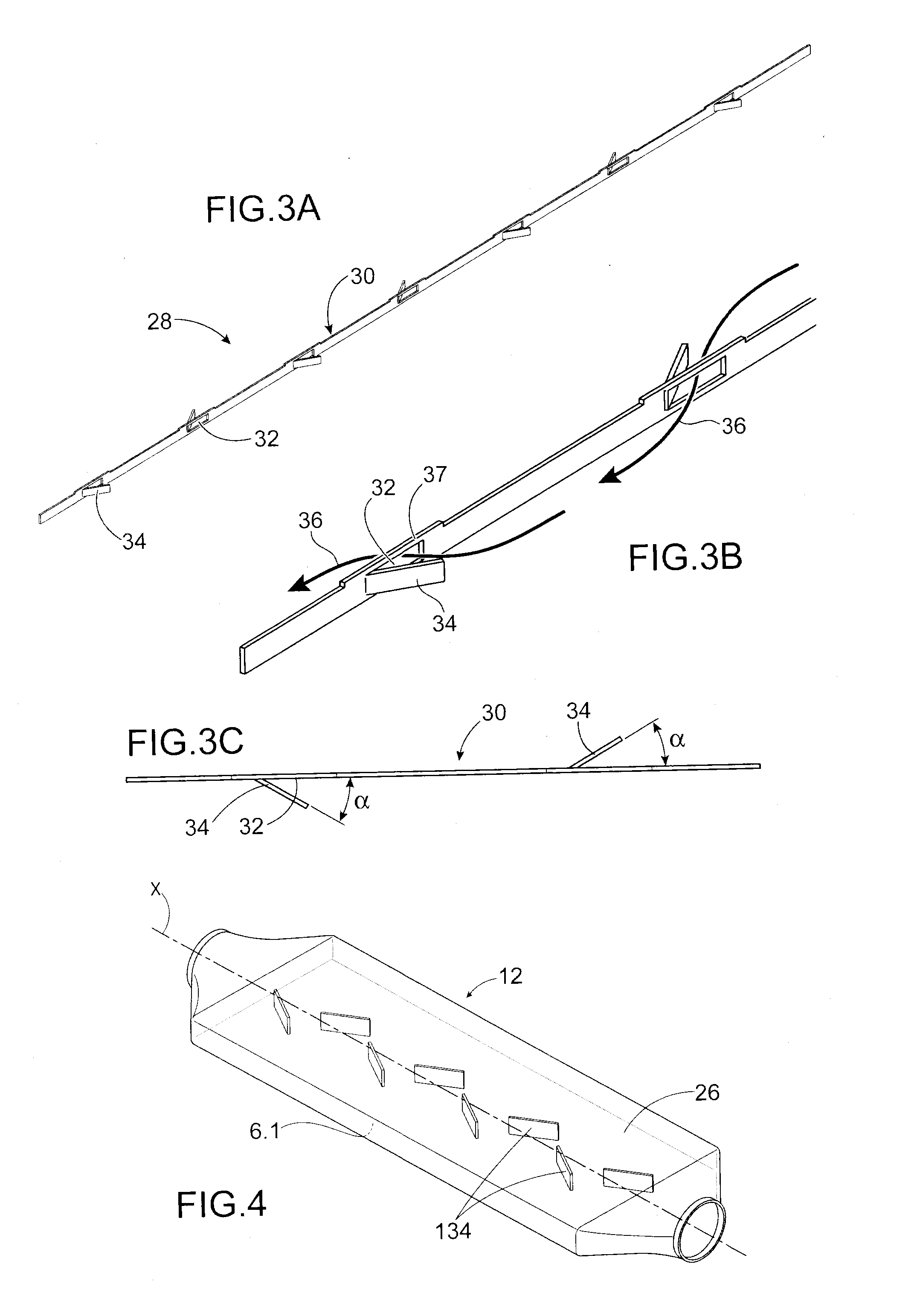
[0023]The aim set out above is attained by a module for the production of an absorber for a solar receiver of a thermal power plant comprising a wall which is roughly flat, and the outer face of which is intended to receive the luminous flux, a wall opposite said wall, and side walls, where said walls define a single channel for the flow of a pressurised heat transfer fluid, and where the wall the face of which is intended to receive the luminous flux and the wall opposite the latter are connected mechanically by means installed in the flow of the fluid, so as to keep the absorber pressurised. The module according to the invention also comprises means for reblending the fluid in the single channel, homogenising the temperature of the fluid, and preventing the appearance of hot points.

[0024]In a particularly advantageous manner, the elements mechanically connecting the two walls also form deflectors for the fluid, so as to reblend the fluid within the module.

[0025]The two mechanicall...


PUM

PropertyMeasurementUnit
emissivityaaaaaaaaaa
temperatureaaaaaaaaaa

Abstract

An absorber for a solar receiver with a casing of lengthways axis including at a first lengthways end, a collector to supply a heat transfer fluid; and at a second lengthways end, a collector for evacuating the heat transfer fluid. The casing includes a first wall having a face intended to be subjected to a luminous flux, a second wall facing the first wall, and side walls connecting said the first and second walls. The casing is formed by at least one rib extending lengthways, and attached to the first and to the second wall. The at least one rib includes windows, and deflectors associated with the windows. The deflectors cause a portion of the heat transfer fluid to flow through the windows, causing reblending of the heat transfer fluid.

Description

TECHNICAL FIELD AND PRIOR ART[0001]The present invention relates to a thermal absorber for a solar receiver of a solar power plant and to a solar receiver for a solar power plant comprising at least one such absorber, in particular for a Fresnel-type concentrating solar power plant.[0002]Concentrating thermal solar technology consists in using solar radiation to heat a heat transfer fluid used as the heat source in a thermodynamic cycle. Concentration enables relatively high temperatures to be attained, and thus relatively substantial thermodynamic conversion efficiencies to be enjoyed. The developed technologies are distinguished by the means used to concentrate the solar rays, by the means by which heat is transferred, and possibly by the means used to store heat, i.e. the heat transfer fluid used and thermodynamic conversion means which are, for example, steam turbines, gas turbines or Stirling engines.[0003]There are typically four families of Concentrating Solar Power (CSP) sys...

Claims


Application Information

Patent Timeline
Patent Type & Authority Applications(United States)
IPC IPC(8): F24J2/20B21D53/02F24J2/10F24S10/50F24S10/55F24S20/20F24S23/70F24S23/77
CPCF24J2/07F24J2/1047F24J2/50F24J2002/108F24J2002/4603Y10T29/49355Y02E10/41B21D53/02F24J2/10F24J2/202F24J2002/4656F28F13/12F24S10/502F24S20/20F24S23/70F24S80/50F24S2023/872F24S2080/03F24S2080/05F24S2080/09Y02E10/44Y02E10/40
Inventor FOURMIGUE, JEAN-FRANCOISBRUCH, ARNAUDCIGNA, JULIENCOUTURIER, RAPHAELROUX, GUILHEM
Owner COMMISSARIAT A LENERGIE ATOMIQUE ET AUX ENERGIES ALTERNATIVES
Learn More