Harness

a technology of harnesses and back plates, applied in the field of harnesses, can solve the problems of imposing a burden on the operator, the back plate may not fit in the optimal state of every operator, and the weight of the power tool cannot be sufficiently distributed, so as to achieve the effect of reducing the burden on the operator and simple structur

Inactive Publication Date: 2013-05-16
MAKITA CORP
View PDF11 Cites 17 Cited by
  • Summary
  • Abstract
  • Description
  • Claims
  • Application Information

AI Technical Summary

Benefits of technology

[0006]The present invention was devised in view of the above problems, and it is an object of the present invention to provide a harness having a simple structure and capable of reducing a burden on the operator.
[0011]According to the first aspect of the present invention, the harness is structured so that the back plate is pulled toward the operator's back by merely adjusting, with the adjusting member, the length of the belt connecting the back plate to the shoulder strap pads. Thus, the back plate can be brought into close contact with the operator's back by using this simple structure. As a result, the weight of the power tool is distributed to the back plate, whereby the burden on the operator can be reduced.
[0012]According to the second aspect of the present invention, the weight of the power tool can be distributed to both shoulders of the operator via the pair of shoulder strap pads. Thus, the load is not intensively applied to one of the shoulders of the operator, and the burden on the operator's shoulders can be reduced.
[0013]According to the third aspect of the present invention, the narrow portion provided in the upper part of the back plate has a lower second moment of area than the lower part of the back plate. Thus, the upper part of the back plate is more easily bent than the lower part of the back plate. Accordingly, the upper part of the back plate can be easily pulled toward the operator's back by adjusting, with the adjusting member, the length of the belt connecting the narrow portion to the shoulder strap pad.
[0014]According to the fourth aspect of the present invention, the hole that allows the operator to carry the back plate in his / her hand is provided in the back plate, and the lateral dimension of the hole is larger than that of the operator's hand. Thus, an opening portion formed by the hole occupies a relatively large proportion of the lateral dimension of the back plate. Accordingly, rigidity of the back plate can be sufficiently reduced near the hole. Moreover, in the back plate, the hole is provided above the position where the shoulder strap pads are fixed to the back plate. Accordingly, the back plate can be bent near the hole by adjusting the length of the belt. The back plate is thus brought into close contact with the back of the operator, and the weight of the power tool is distributed to the back plate, whereby the burden on the operator can be reduced.

Problems solved by technology

However, even though the back plate of the harness has a curved shape, the back plate may not fit on the back of every operator in an optimal state.
As a result, the weight of the power tool cannot be sufficiently distributed by the back plate, which may impose a burden on the operator due to such an uneven load.
Moreover, in order to allow the shoulder plates to fit on the operator's shoulders, the plurality of grooves need be provided in the shoulder plates, which may complicate the structure of the harness.

Method used


Image

  • Harness
  • Harness
  • Harness

Examples


Embodiment Construction

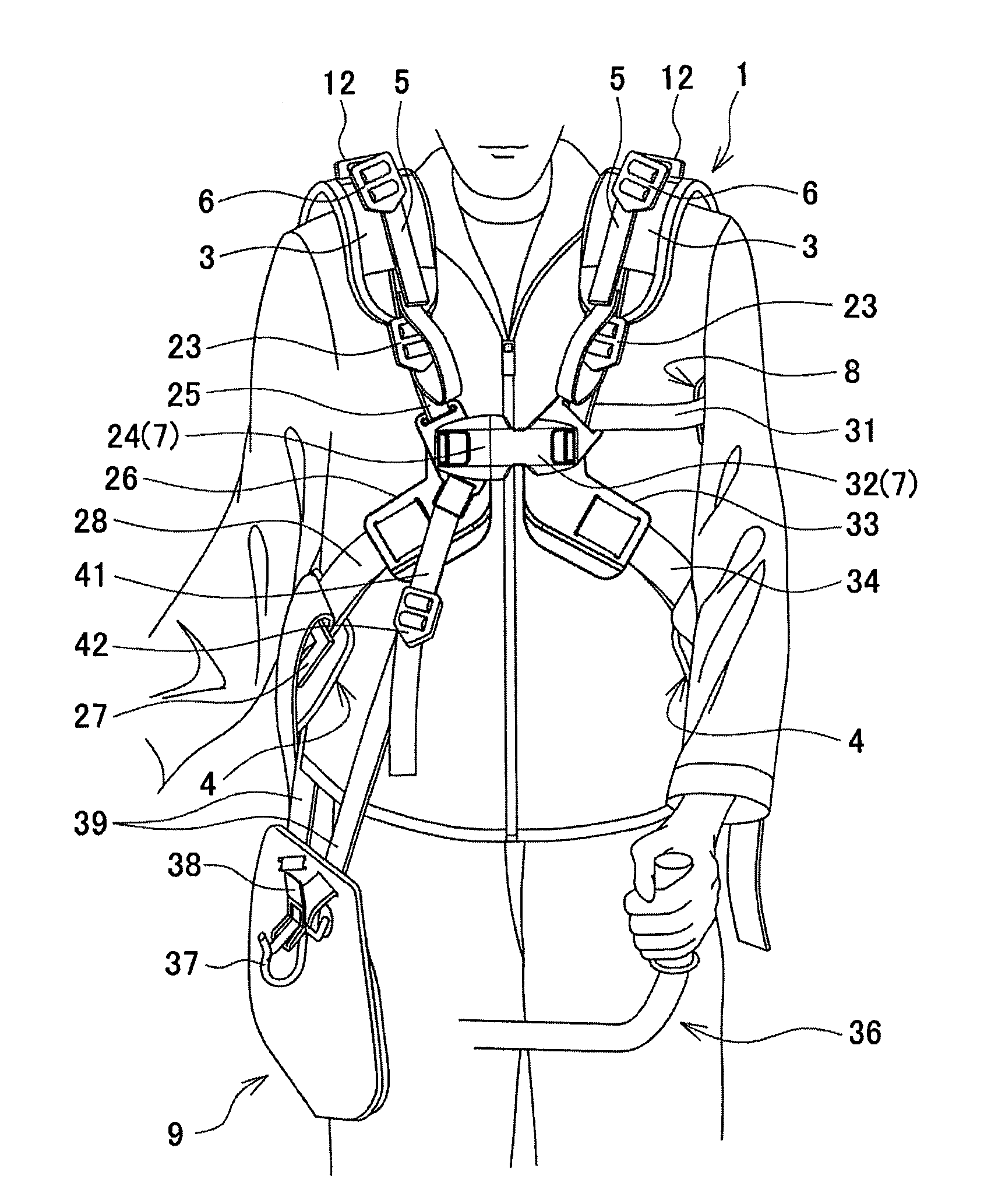
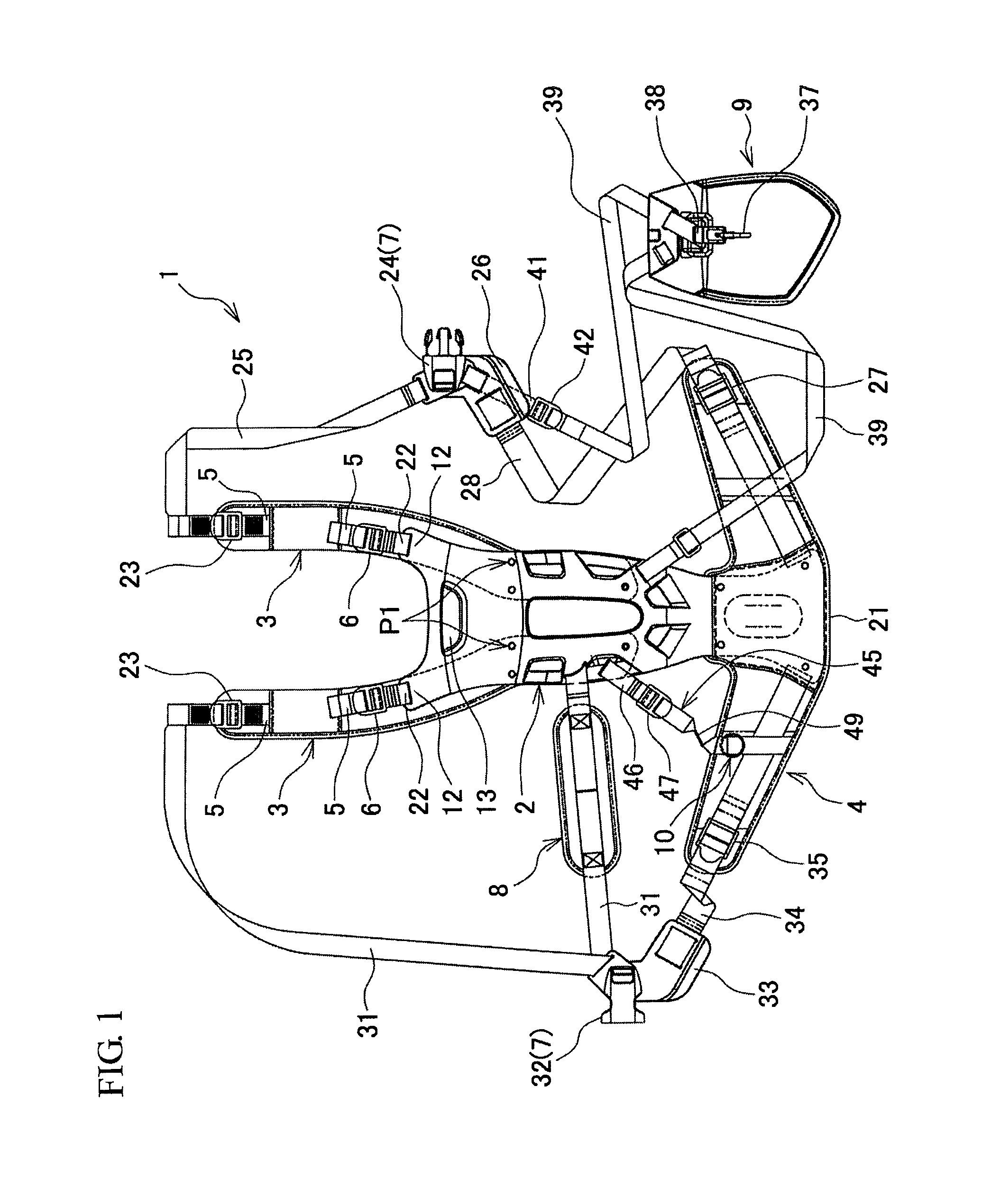
[0023]An embodiment of the present invention will be described with reference to FIGS. 1 to 7. A harness 1 shown in FIG. 1 is equipment the operator wears in order to support a power tool such as brush cutter, and includes a back plate 2, shoulder strap pads 3, 3, a waist pad 4, shoulder strap belts 5, 5, first belt length adjusters 6, 6, a buckle 7, a side pad 8, a support member 9, and a hanging ring 10.

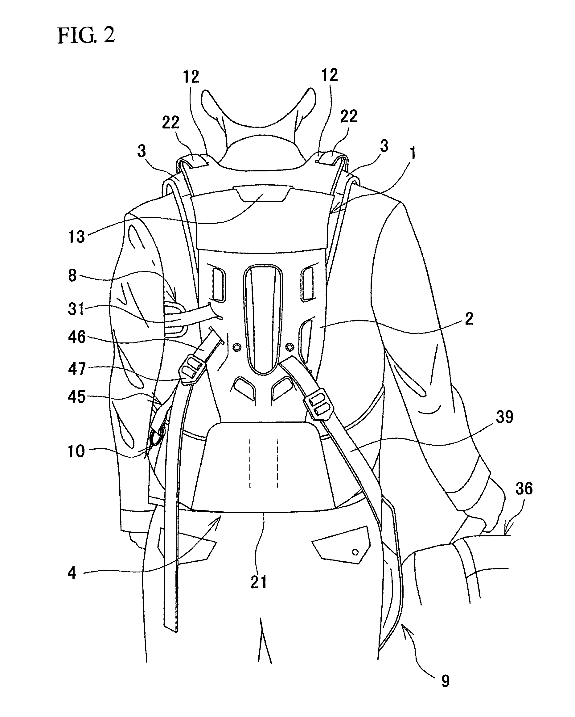
[0024]As shown in FIGS. 2 and 3, when the operator wears the harness 1, the back plate 2 is placed on the back of the operator. The back plate 2 is a flexible plate-like member extending in the vertical direction and made of a synthetic resin. The back plate 2 has a pair of narrow portions 12 (see FIGS. 1 and 2) protruding upward from the left and right upper ends of the back plate 2 and having a smaller lateral dimension than a lower part of the back plate 2. As shown in FIGS. 1 and 2, a hole 13 that allows the operator to carry the back plate 2 in his / her hand is formed in an upp...


PUM


Abstract

A harness is worn by an operator to support a power tool on a lateral side of the operator, and includes a back plate extending in a vertical direction and placeable on a back of the operator, and a pair of shoulder strap pads that contact both shoulders of the operator. The shoulder strap pads are fixed to the back plate, and the back plate is connected to each of the shoulder strap pads by a belt. The harness further includes an adjusting member with which a length of the belt is adjustable, and a position of the back plate is adjustable toward the back of the operator by adjusting the length of the belt using the adjusting member.

Description

BACKGROUND OF THE INVENTION[0001]This application claims the benefit of Japanese Patent Application Number 2011-247807 filed on Nov. 11, 2011, the entirety of which is incorporated by reference.TECHNICAL FIELD[0002]The present invention relates to harnesses the operator wears in order to support a power tool such as a brush cutter or a blower.BACKGROUND ART[0003]When working with a power tool such as a brush cutter or a blower, the operator wears work equipment called “harness” in view of workability, and for example, the operator engages the power tool with the harness by hanging the power tool therefrom, so that he / she can support the weight of the power tool with his / her body. As described in Japanese Patent Application Publication No. 2010-252689 (JP 2010-252689 A), a known harness includes a back plate that is placed on the back of the operator, shoulder plates that are formed integrally with the back plate and that together with shoulder strap belts are placed on the shoulders...

Claims


Application Information

Patent Timeline
Patent Type & Authority Applications(United States)
IPC IPC(8): F16M13/04
CPCA01D34/902A45F3/14A45F2003/146
Inventor HACHISUKA, TOMOHIRO
Owner MAKITA CORP
Why Eureka
Try Eureka