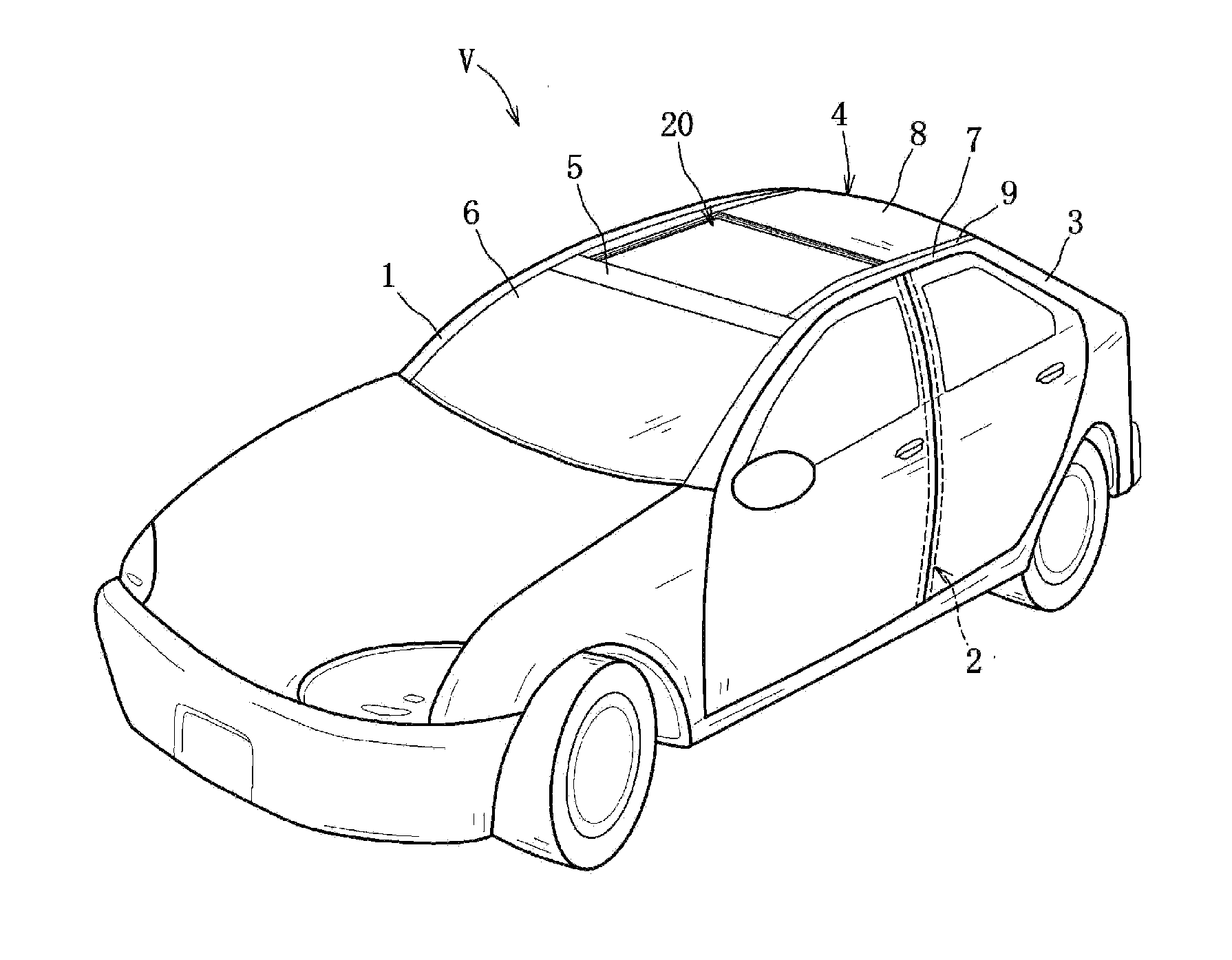
Upper vehicle-body structure of vehicle
a vehicle and upper body technology, applied in the direction of vehicle components, superstructure sub-units, roofs, etc., can solve the problems of not being able to ensure the stability of curtain airbag inflation for both a passenger seated in the front seat and a passenger seated in the rear seat, and the difference in gas supply time between the supply of front-seat airbag and the supply of rear-seat airbag, so as to achieve the effect of stable airbag inflation
- Summary
- Abstract
- Description
- Claims
- Application Information
AI Technical Summary
Benefits of technology
Problems solved by technology
Method used
Image
Examples
embodiment 1
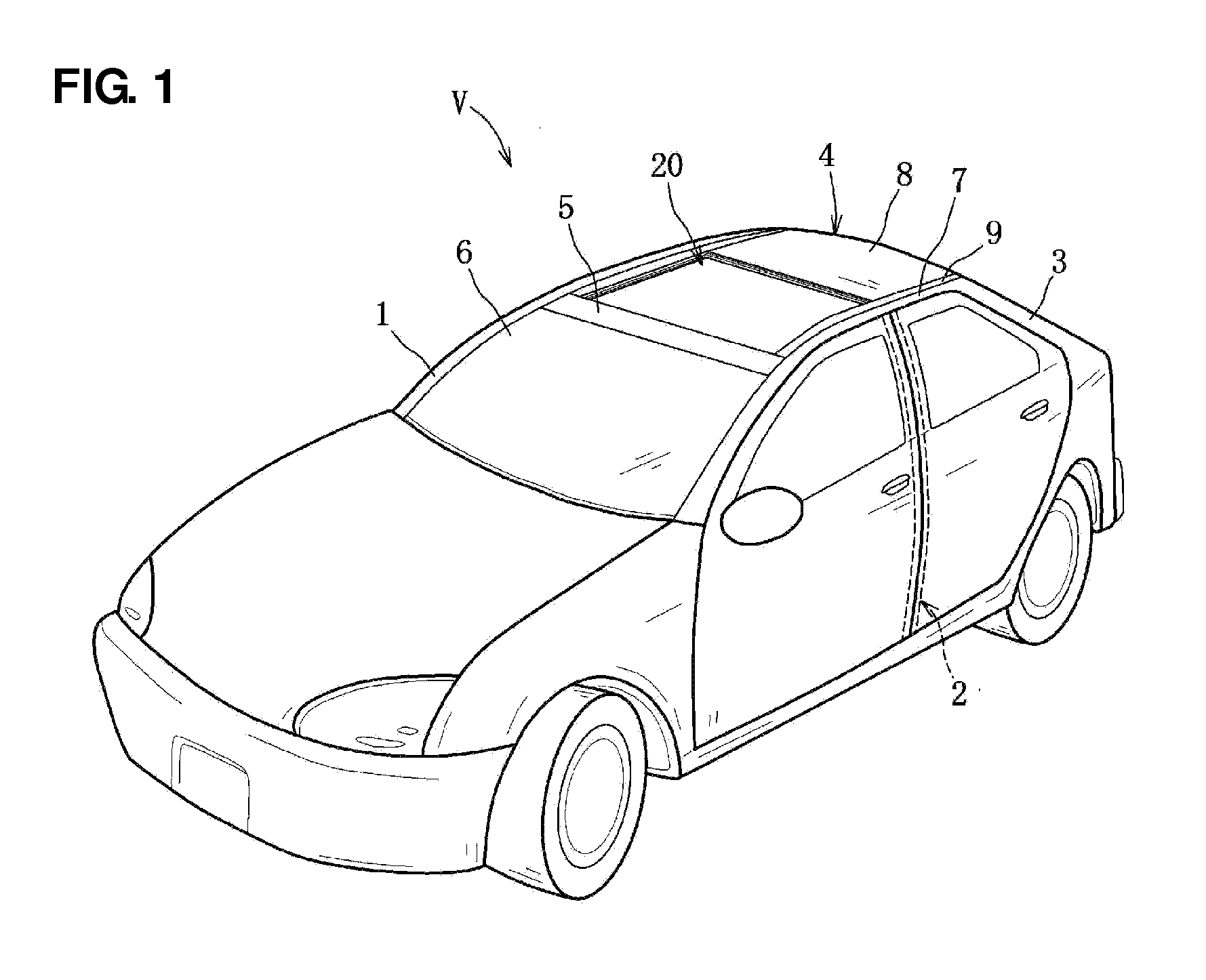
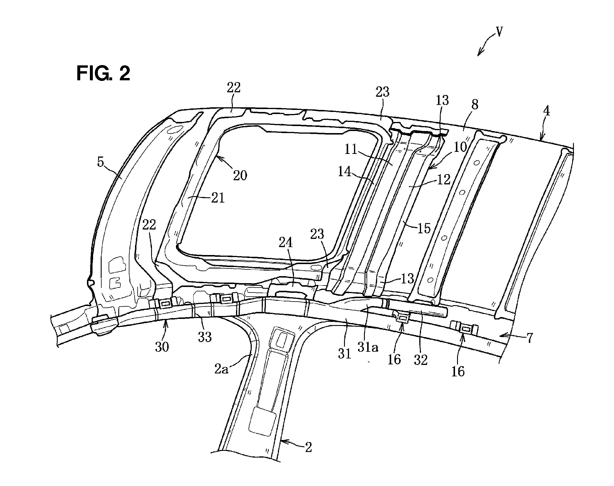
[0030]A first embodiment of the present invention will be described referring to FIGS. 1 through 10. As shown in FIGS. 1 and 2, a vehicle V of the present embodiment comprises a pair of right-and-left front pillars 1, a pair of right-and-left center pillars 2, a pair of right-and-left rear pillars 3, a roof 4 which is equipped with a sunroof unit 20 at its front-side portion, a pair of right-and-left curtain airbag unit 30, and others. As shown in FIG. 1, a front header 5 which extends in a vehicle width direction is provided at an upper end portion of the pair of front pillars 1, to which an upper portion of a windshield (front window glass) 6 is attached.
[0031]As shown in FIGS. 1 and 2, the pair of center pillars 2 is provided at a central position between a frond seat (not illustrated) and a rear seat (not illustrated). As shown in FIG. 6, the right-side center pillar 2 has a closed cross section extending vertically which is formed by a center pillar outer 2a and a center pillar...
embodiment 2
[0056]Next, an upper vehicle-body structure of the vehicle V according to a second embodiment 2 will be described referring to FIG. 11. Only structures of the second embodiment which are different from the above-described first embodiment will be described. The same references are used to denote the same members as the first embodiment, and descriptions of those are omitted.
[0057]A roof reinforcement 10A is arranged in back of the pair of center pillars 2 with an offset distance, and includes a wedge-shaped concave portion 17 which has a wedge-shaped section extending over a vehicle-width-direction whole width. The wedge-shaped concave portion 17 is configured such that its bottom portion slants obliquely rearward and upward, that is—its rear depth is becomes shallower. A front flange 14A and a rear flange 15A are provided at a front end portion and a rear end portion of the wedge-shaped concave portion 17, and joined to a back face of the rear peripheral-frame reinforcing member 23...
PUM
 Abstract
Description
Claims
Application Information
 - R&D
- Intellectual Property
- Life Sciences
- Materials
- Tech Scout
- Unparalleled Data Quality
- Higher Quality Content
- 60% Fewer Hallucinations
Browse by: Latest US Patents, China's latest patents, Technical Efficacy Thesaurus, Application Domain, Technology Topic, Popular Technical Reports.
© 2025 PatSnap. All rights reserved.Legal|Privacy policy|Modern Slavery Act Transparency Statement|Sitemap|About US| Contact US: help@patsnap.com


