
System and Method for Image Editing Using Visual Rewind Operation

a visual rewind operation and image technology, applied in the execution of user interfaces, electronic editing digitised analogue information signals, instruments, etc., can solve the problems of reducing the overall performance of the system, affecting the overall performance, and affecting the effect of the overall performan

Active Publication Date: 2013-05-16
ADOBE INC
View PDF6 Cites 98 Cited by
  • Summary
  • Abstract
  • Description
  • Claims
  • Application Information

AI Technical Summary

Benefits of technology

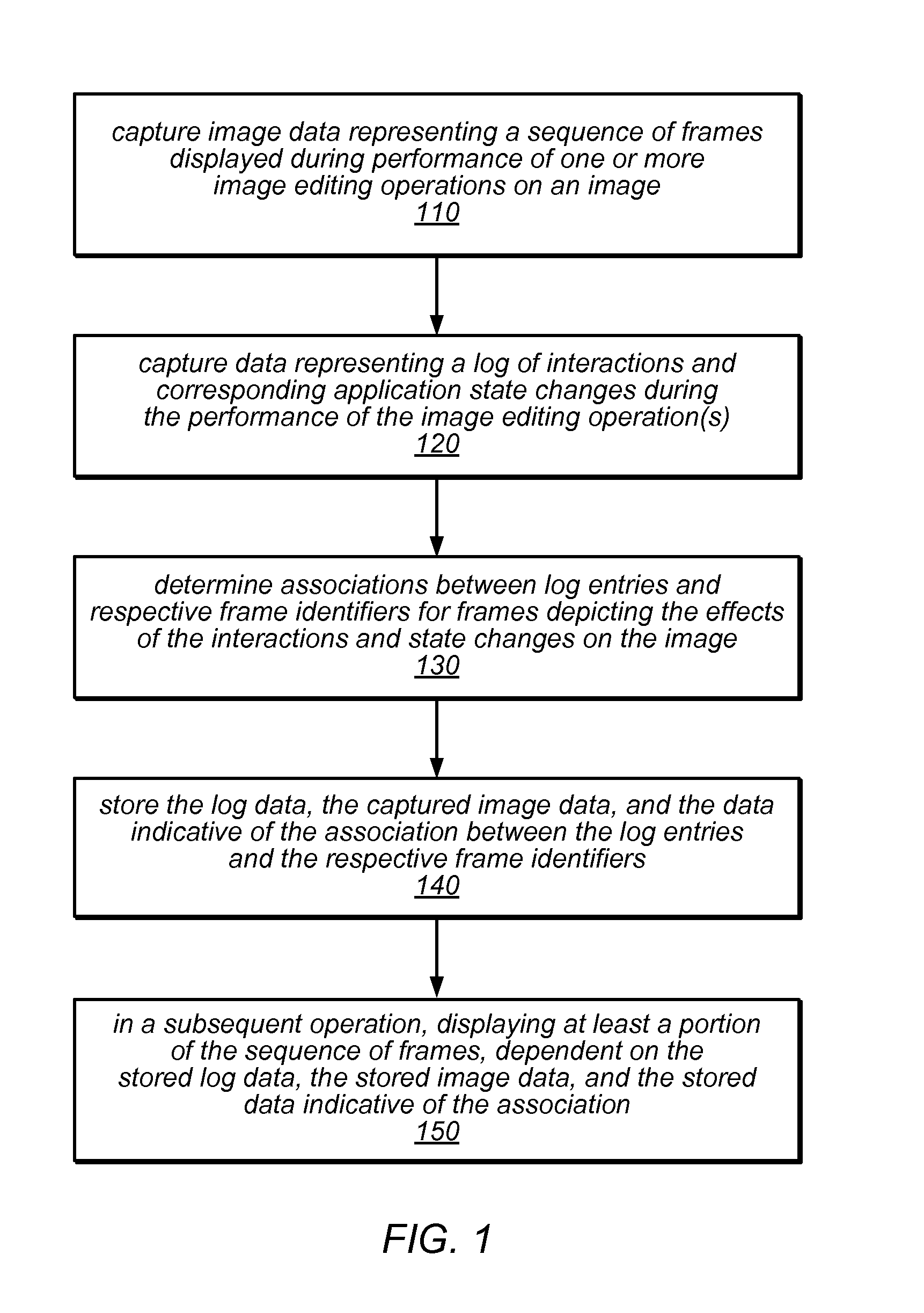
The methods described in this patent text are meant to be implemented as program instructions that can be executed by a CPU or GPU for parallel processing. These methods involve capturing, compressing, and storing image data and interaction logs, as well as using the stored information in a visual rewind operation. The goal is to reduce the impact on the overall performance of the image editing application by off-loading as many of these operations as possible onto the GPU, rather than having them executed by the CPU. This may result in faster and more efficient image editing with reduced impact on the overall user experience.

Problems solved by technology

This method is not effective if more then a couple of changes need to be rolled back.
However, the visual hint for a history state may be nothing more than a very small icon, or generic text string such as “typing” or “brush stroke”, which may quickly lose its uniqueness in the context of a series of such operations.
In typical applications it is not possible to undo portion of a continuous operation (such as a brush stroke in a painting application).
In various embodiments, performing as many of these operations as possible on a GPU may reduce their effect on the overall performance of the interactive image editing application through which they are executed.

Method used


Image

  • System and Method for Image Editing Using Visual Rewind Operation
  • System and Method for Image Editing Using Visual Rewind Operation
  • System and Method for Image Editing Using Visual Rewind Operation

Examples


Embodiment Construction

[0022]In the following detailed description, numerous specific details are set forth to provide a thorough understanding of claimed subject matter. However, it will be understood by those skilled in the art that claimed subject matter may be practiced without these specific details. In other instances, methods, apparatuses or systems that would be known by one of ordinary skill have not been described in detail so as not to obscure claimed subject matter.

[0023]Some portions of the detailed description that follows are presented in terms of algorithms or symbolic representations of operations on binary digital signals stored within a memory of a specific apparatus or special purpose computing device or platform. In the context of this particular specification, the term specific apparatus or the like includes a general purpose computer once it is programmed to perform particular functions pursuant to instructions from program software. Algorithmic descriptions or symbolic representati...


PUM


Abstract

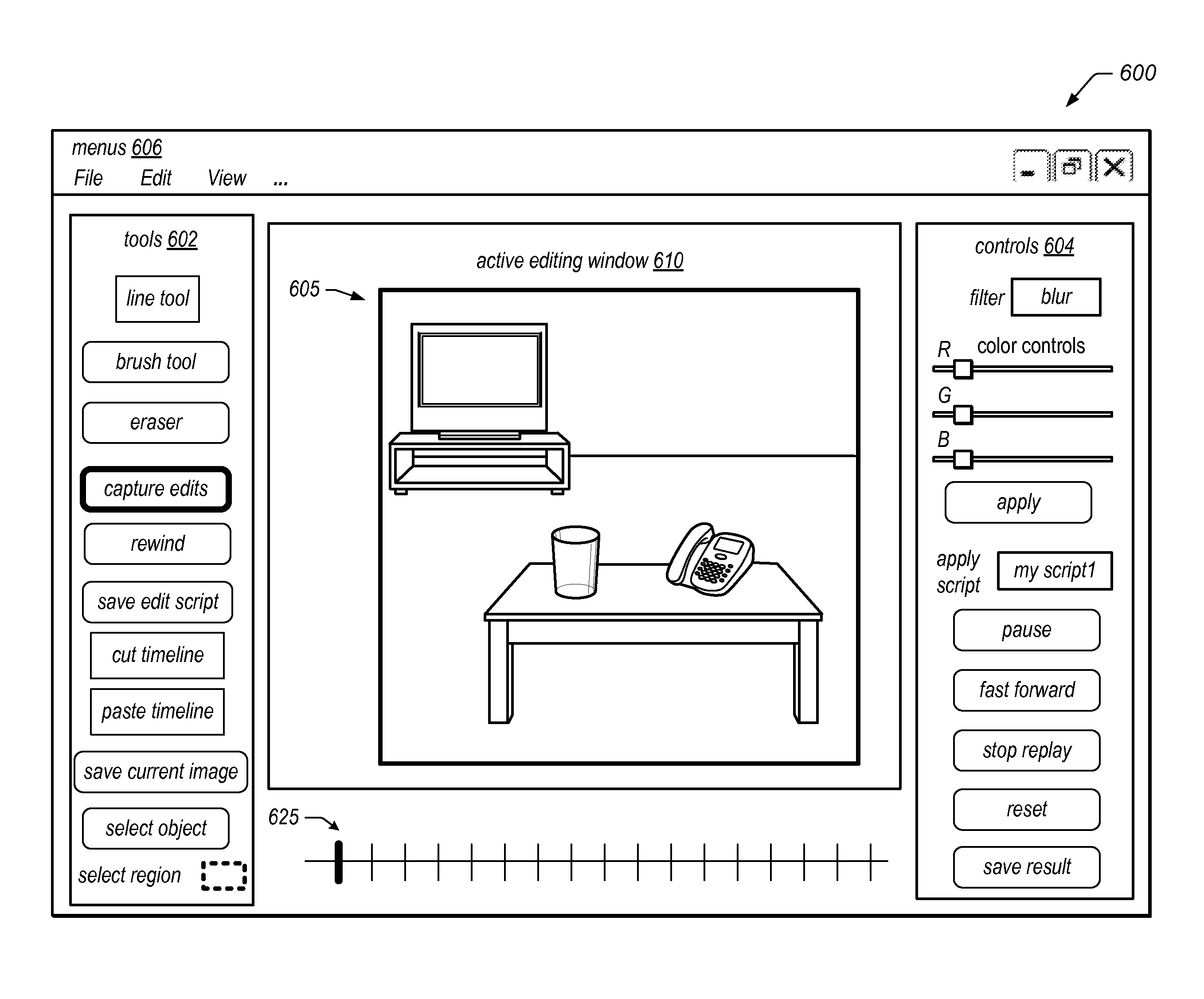
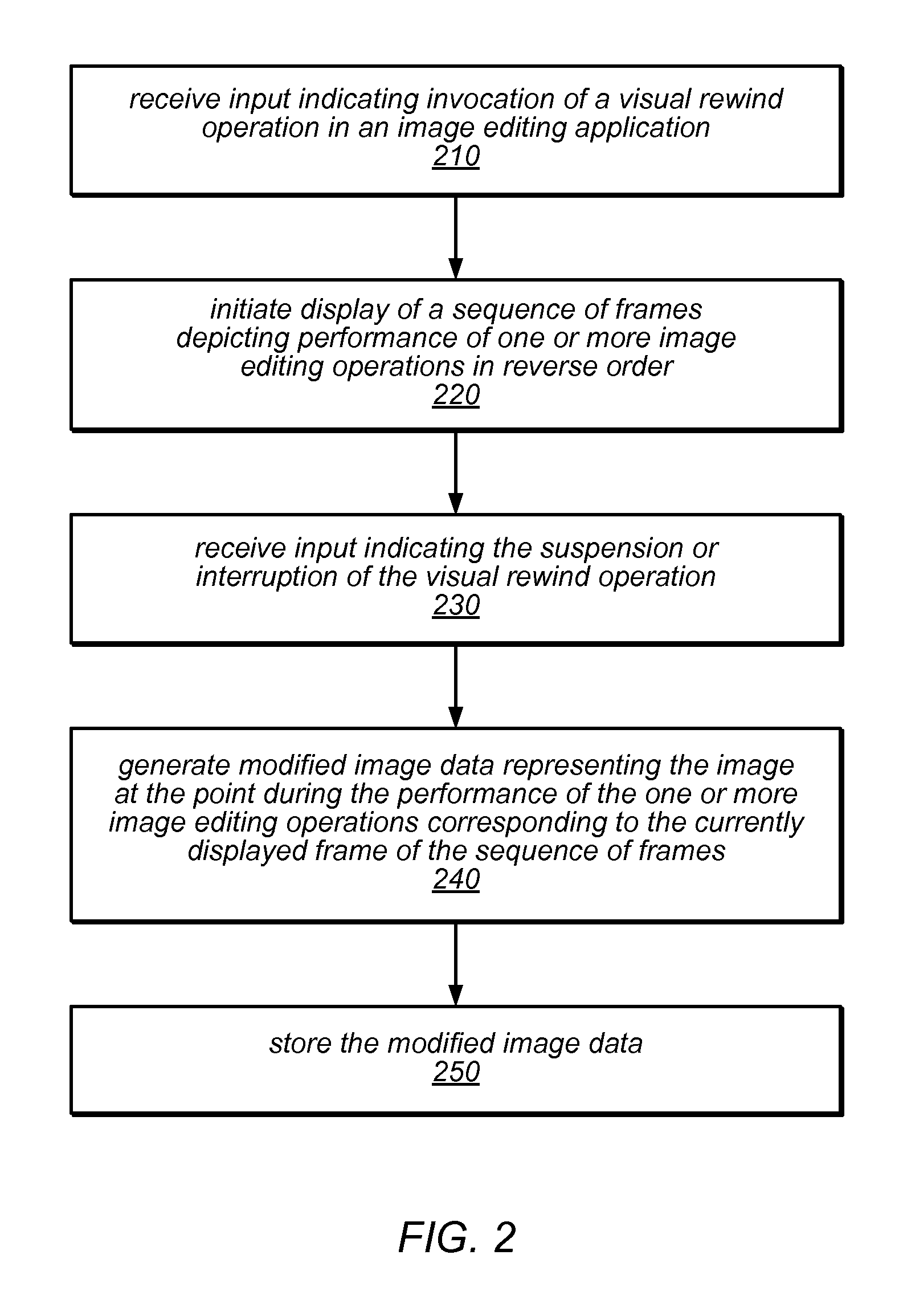
Systems, methods, and computer-readable storage media for performing a visual rewind operation in an image editing application may include capturing, compressing, and storing image data and interaction logs and correlations between them. The stored information may be used in a visual rewind operation, during which a sequence of frames (e.g., an animation) depicting changes in an image during image editing operations is displayed in reverse order. In response to navigating to a point in the animation, data representing the image state at that point may be reconstructed from the stored data and stored as a modified image or a variation thereof. The methods may be employed in an image editing application to provide a partial undo operation, image editing variation previewing, and / or visually-driven editing script creation. The methods may be implemented as stand-alone applications or as program instructions implementing components of a graphics application, executable by a CPU and / or GPU.

Description

BACKGROUNDDescription of the Related Art[0001]Graphic applications include an ever-increasing number of image editing features, such as various filtering options and resizing operations (e.g., for cropping, expanding, or reducing an image). In order to undo or redo an image editing operation, a typical image editing application may provide a simple undo command. A simple undo command may provide a coarse, non-intuitive method to rollback changes. This method is not effective if more then a couple of changes need to be rolled back. Currently, the user corrects mistakes by choosing undo from a menu, or by clicking on a history state in the history palette of an application. However, the visual hint for a history state may be nothing more than a very small icon, or generic text string such as “typing” or “brush stroke”, which may quickly lose its uniqueness in the context of a series of such operations. Navigating an undo / redo queue limits the operation to be undone or redone to certai...

Claims


Application Information

Patent Timeline
IPC IPC(8): G09G5/00
CPCG11B27/034G11B27/34G06T13/80G06T11/60G06F3/04845G06F3/023G06F3/04883G06F3/0362G06F3/04847G06F9/451G06V20/46
Inventor HARRIS, JERRY G.BYER, SCOTT L.SCHAEM, STEPHAN D.
Owner ADOBE INC
Learn More