

Optical lens system for image taking
- Summary
- Abstract
- Description
- Claims
- Application Information
AI Technical Summary
Benefits of technology
Problems solved by technology
Method used
Image

Examples
first embodiment
The First Embodiment
Embodiment 1
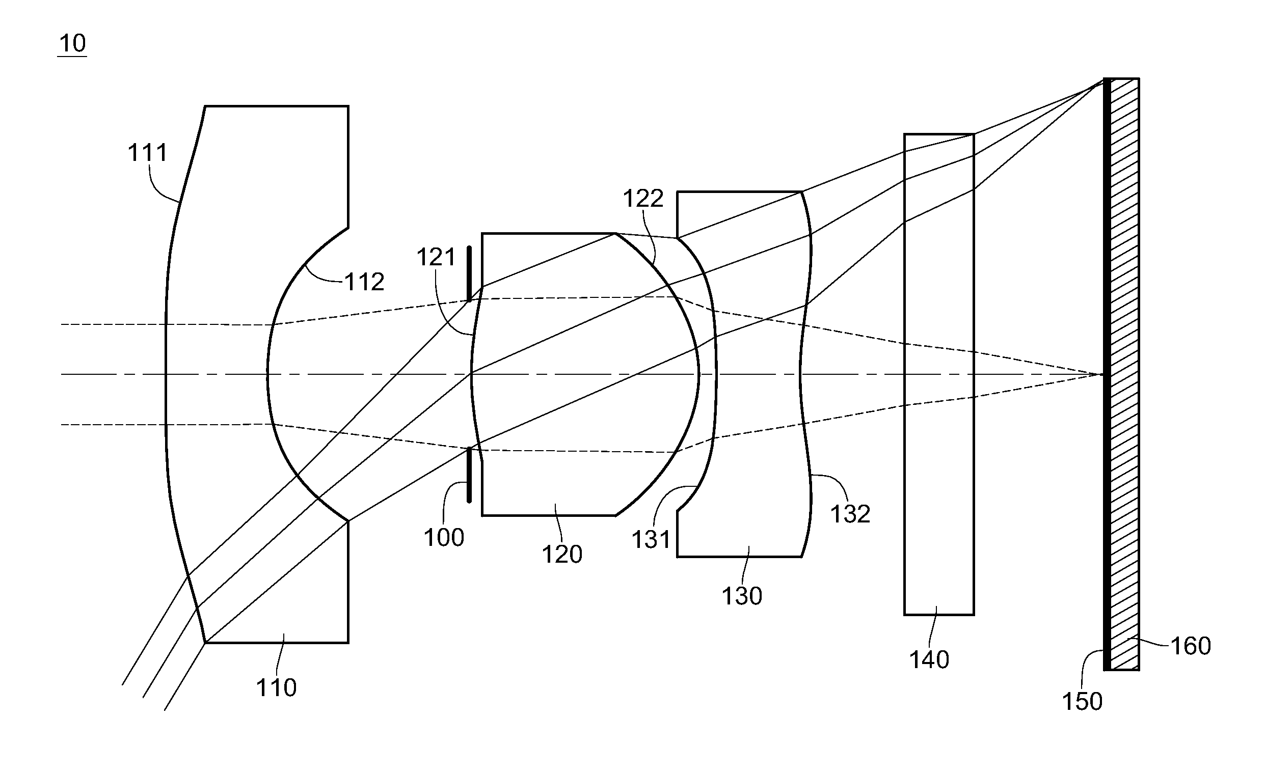
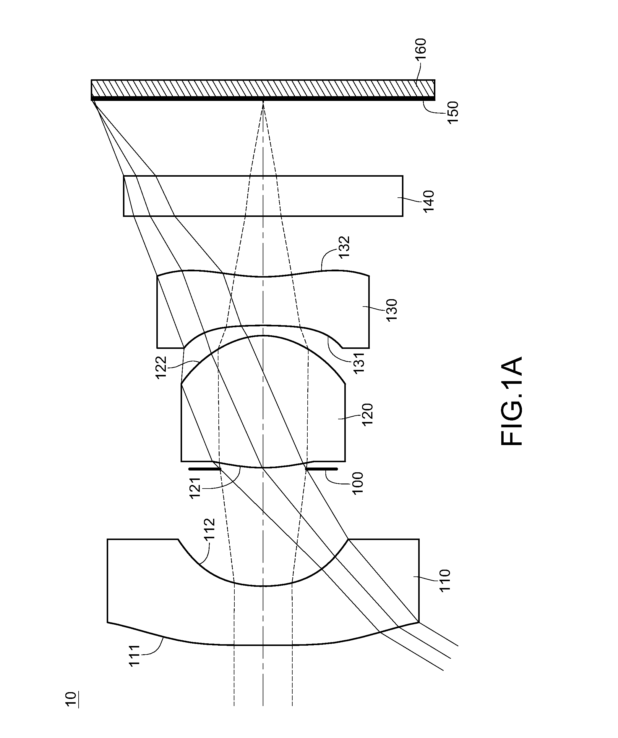
[0068]FIG. 1A is a schematic structural view of the first embodiment of the optical lens system for image taking. In this embodiment, light having the reference wavelength of 587.6 nm is incident on the optical lens system for image taking 10. However, the reference wavelength of the light does not intend to limit the disclosure. In some embodiments, light with different wavelength is used based on various demands.
[0069]In this embodiment, the refractive power of the first lens element 110 is negative; the refractive power of the second lens element 120 is positive; the refractive power of the third lens element 130 is negative. The image-side surface 112 is concave, the object-side surface 111 near the optical axis is concave and the object-side surface 111 away from the optical axis is convex. The object-side surface 121 and the image-side surface 122 are convex. The object-side surface 131 is concave, the image-side surface 132 near the optical axi...
second embodiment
The Second Embodiment
Embodiment 2
[0083]FIG. 2A is a schematic structural view of the second embodiment of the optical lens system for image taking. The specific implementation and elements of the second embodiment are substantially the same as those in the first embodiment. The element symbols in the second embodiment all begin with “2” which correspond to those in the first embodiment with the same function or structure. For conciseness, only the differences are illustrated below, and the similarities will not be repeated herein.
[0084]In this embodiment, for example, the reference wavelength of the light received by the optical lens system for image taking 20 is 587.6 nm.
[0085]In this embodiment, the refractive power of a first lens element 210 is negative; the refractive power of a second lens element 220 is positive; the refractive power of a third lens element 230 is negative. The first lens element 210 has an object-side surface 211 and a concave image-side surface 212. The obj...
third embodiment
The Third Embodiment
Embodiment 3
[0093]FIG. 3A is a schematic structural view of the third embodiment of the optical lens system for image taking. The specific implementation and elements of the third embodiment are substantially the same as those in the first embodiment. The element symbols in the third embodiment all begin with “3” which correspond to those in the first embodiment with the same function or structure. For conciseness, only the differences are illustrated below, and the similarities will not be repeated herein.
[0094]In this embodiment, for example, the reference wavelength of the light received by the optical lens system for image taking 30 is 587.6 nm.
[0095]In this embodiment, the refractive power of a first lens element 310 is negative; the refractive power of a second lens element 320 is positive; the refractive power of a third lens element 330 is negative. The first lens element 310 has an object-side surface 311 and a concave image-side surface 312. The object-...
PUM
 Abstract
Description
Claims
Application Information