Air Blowing Unit For Vehicle
a technology of air blowing unit and air blowing passage, which is applied in the direction of machines/engines, stators, liquid fuel engines, etc., can solve the problems of catching fire, impeller and motor flange collision due to vibration or increase in the locking of the impeller rotation, and preventing the formation of a vortex of air. , to achieve the effect of suppressing air in the air blowing passage, suppressing air, and preventing the formation of a vortex of air
- Summary
- Abstract
- Description
- Claims
- Application Information
AI Technical Summary
Benefits of technology
Problems solved by technology
Method used
Image
Examples
embodiment 1
[0044]In the embodiment 1, as shown in FIG. 3, in the case 4, an inner surface of the wall portion 17 and an inner surface of the motor flange 14 are arranged on the substantially same line, and a projecting portion 20 is formed on a connecting portion between the wall portion 17 and the motor flange 14 as an air backflow prevention means which prevents air from flowing back to a gap space 30 formed between a flange-side surface of the impeller 2 and the inner surface of the motor flange 14.
[0045]The projecting portion 20 is formed in an annular shape outside a radial outer end of the impeller 2 in the radial direction, and is not positioned in the gap space 30 formed between the flange-side surface of the impeller 2 and the inner surface of the motor flange 14. Further, the projecting portion 20 projects in the inside of the air blowing passage 15 from the inner surface of the wall portion 17 in a state where the projecting portion 20 is integrally formed with the wall portion 17. ...
embodiment 2
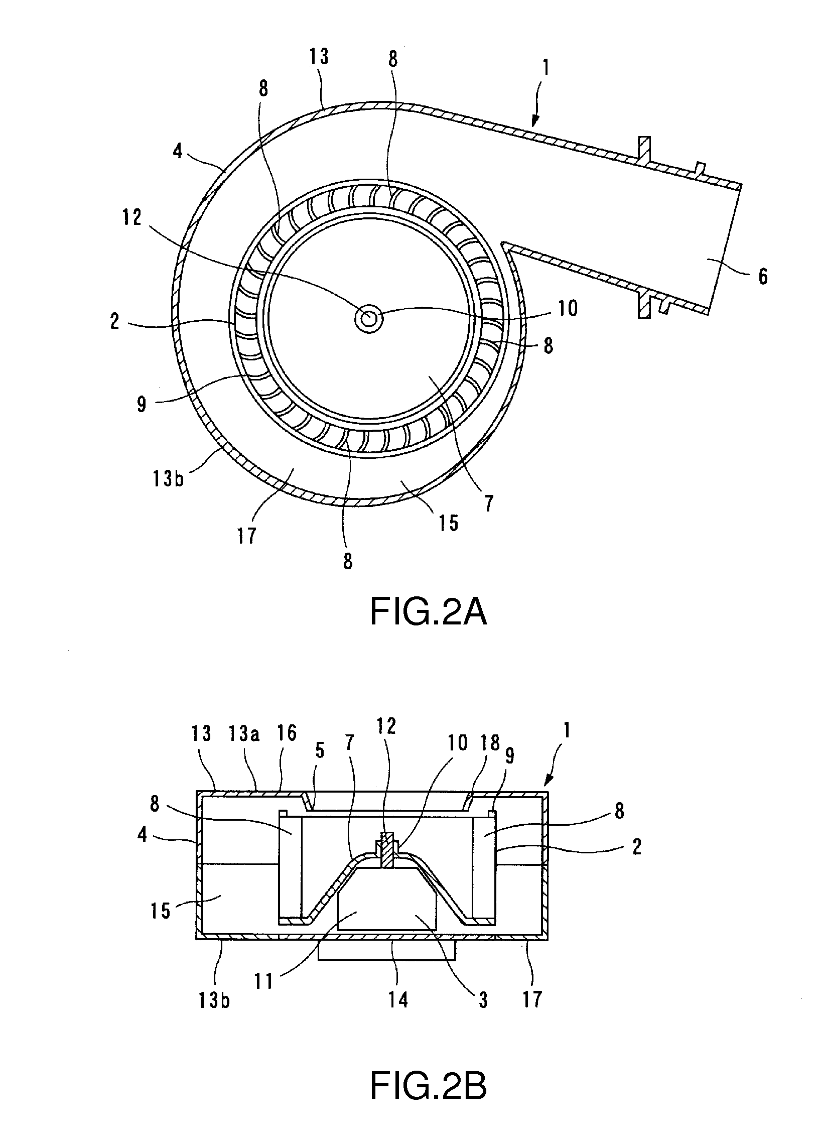
[0051]FIG. 4 shows the embodiment 2 of the invention. Hereinafter, the embodiment 2 of the invention is explained in conjunction with FIG. 4. Since the basic constitution of an air blowing unit 1 is substantially equal to the basic constitution of the air blowing unit 1 of the embodiment 1 shown in FIG. 1 and FIG. 2, in principle, a point which makes the embodiment 2 differ from the embodiment 1 is mainly explained, and the constitution of the embodiment 2 equal to the constitution of the embodiment 1 is given the same symbol and the explanation of the constitution is omitted.
[0052]Also in this embodiment 2, in a case 4, an inner surface of a wall portion 17 and an inner surface of a motor flange 14 are arranged on the substantially same line, and a projecting portion 20 is formed on a connecting portion between the wall portion 17 and the motor flange 14 as an air backflow prevention means which prevents the air from flowing back to a gap space 30 formed between a flange-side surfa...
embodiment 3
[0056]FIG. 5 shows the embodiment 3 of the invention. Hereinafter, the embodiment 3 of the invention is explained in conjunction with FIG. 5. Since the basic constitution of an air blowing unit 1 is substantially equal to the basic constitution of the air blowing unit 1 of the embodiment 1 shown in FIG. 1 and FIG. 2, in principle, a point which makes the embodiment 3 differ from the embodiment 1 is mainly explained, and the constitution of the embodiment 3 equal to the constitution of the embodiment 1 is given the same symbol and the explanation of the constitution is omitted.
[0057]Also in this embodiment 3, in the same manner as the embodiment 1 and the embodiment 2, an inner surface of a wall portion 17 and an inner surface of a motor flange 14 are arranged on the substantially same line, and a projecting portion 20 is formed on a connecting portion between the wall portion 17 and the motor flange 14 as an air backflow prevention means which prevents the air from flowing back to a...
PUM
 Abstract
Description
Claims
Application Information
 - R&D
- Intellectual Property
- Life Sciences
- Materials
- Tech Scout
- Unparalleled Data Quality
- Higher Quality Content
- 60% Fewer Hallucinations
Browse by: Latest US Patents, China's latest patents, Technical Efficacy Thesaurus, Application Domain, Technology Topic, Popular Technical Reports.
© 2025 PatSnap. All rights reserved.Legal|Privacy policy|Modern Slavery Act Transparency Statement|Sitemap|About US| Contact US: help@patsnap.com


