Plug connector with external contacts

a plug connector and external contact technology, applied in the field of electrical connectors, can solve the problems of inconsistent feel, insufficient insertion and extraction of the plug connector, and the length of the current 3.5 mm and even 2.5 mm audio connectors, and achieve the effect of reducing the length and thickness of the plug

Active Publication Date: 2013-05-16
APPLE INC
View PDF10 Cites 45 Cited by
  • Summary
  • Abstract
  • Description
  • Claims
  • Application Information

AI Technical Summary

Benefits of technology

[0010]In view of the shortcomings in currently available electronic connectors as described above, some embodiments of the present invention relate to improved plug connectors that have a reduced plug length and thickness, an intuitive insertion orientation and a smooth, consistent feel when inserted and extracted from its corresponding receptacle connector. Additionally, some embodiments of plug connectors according to the present invention only include external contacts and do not include contacts positioned within an internal cavity that is prone to collecting and trapping debris.

Problems solved by technology

The diameter and length of current 3.5 mm and even 2.5 mm audio connectors are limiting factors in making such devices smaller and thinner and in allowing the displays to be larger for a given form factor.
Many standard data connectors are also only available in sizes that are limiting factors in making portable electronic devices smaller.
Also, and in addition to the orientation issue, even when connector 30 is properly aligned, the insertion and extraction of the connector is not precise, and may have an inconsistent feel.
Further, even when the connector is fully inserted, it may have an undesirable degree of wobble that may result in either a faulty connection or breakage.
Many other commonly used data connectors, including standard USB connectors, mini USB connectors, FireWire connectors, as well as many of the proprietary connectors used with common portable media electronics, suffer from some or all of these deficiencies or from similar deficiencies.

Method used


Image

  • Plug connector with external contacts
  • Plug connector with external contacts
  • Plug connector with external contacts

Examples


Embodiment Construction

[0063]The present invention will now be described in detail with reference to certain embodiments thereof as illustrated in the accompanying drawings. In the following description, numerous specific details are set forth in order to provide a thorough understanding of the present invention. It will be apparent, however, to one skilled in the art, that the present invention may be practiced without some or all of these specific details. In other instances, well known details have not been described in detail in order not to unnecessarily obscure the present invention.

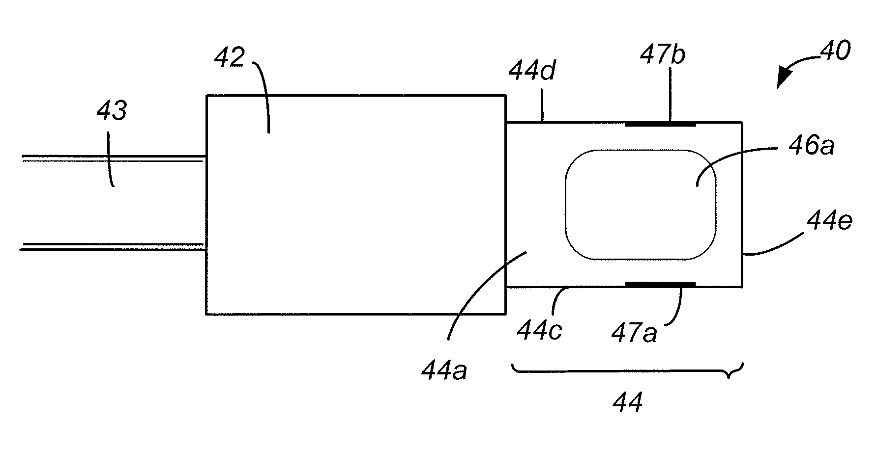
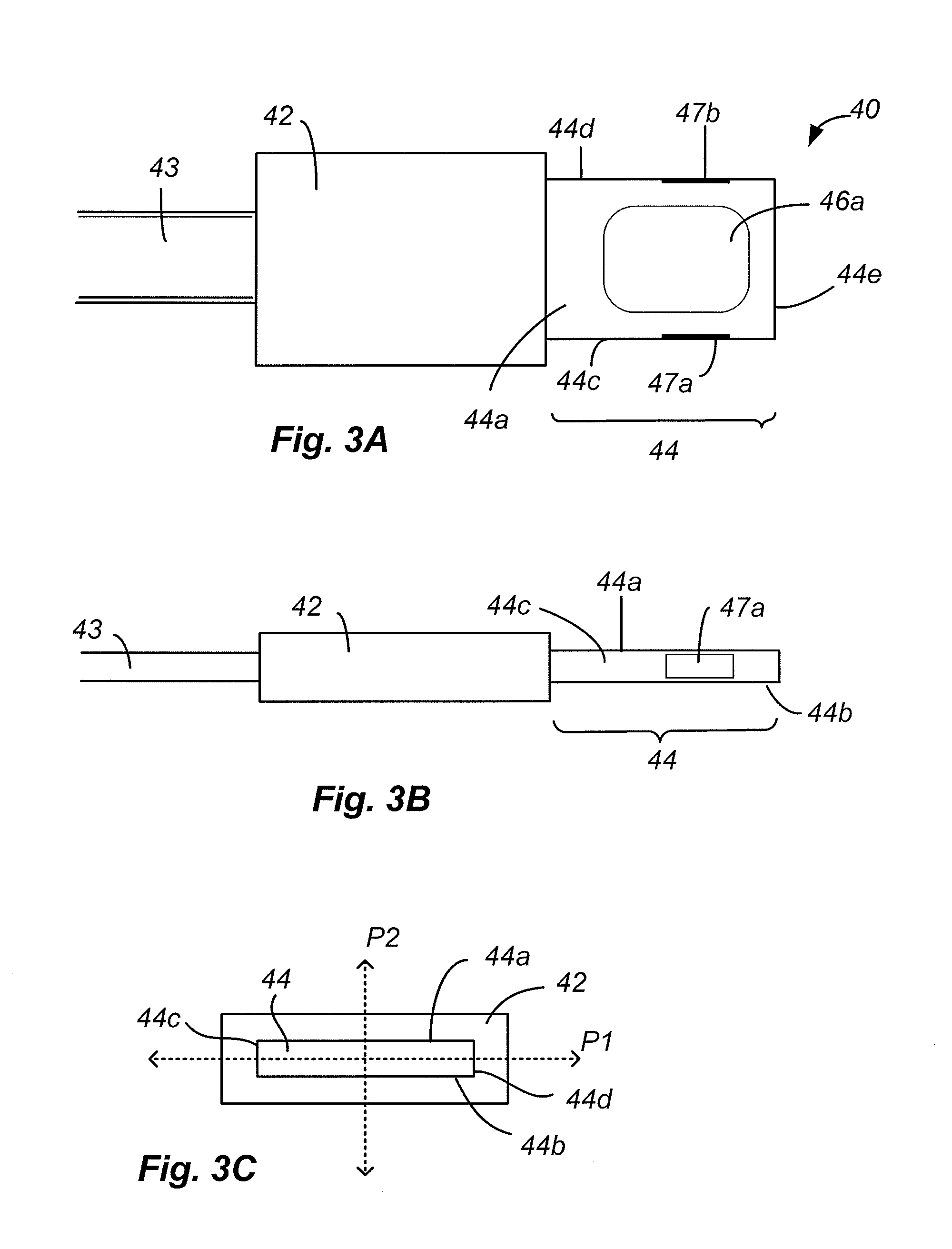
[0064]In order to better appreciate and understand the present invention, reference is first made to FIGS. 3A-3C, which are simplified top, side and front views, respectively, of a dual orientation plug connector 40 according to one embodiment of the present invention. Connector 40 includes a body 42 and a tab portion 44 that extends longitudinally away from body 42 in a direction parallel to the length of the connector ...


PUM


Abstract

A dual orientation connector having a connector tab with first and second major opposing sides and a plurality of electrical contacts carried by the connector tab. The plurality of contacts includes a first set of external contacts formed at the first major side and a second set of external contacts formed at the second major side. Each individual contact in the first plurality of contacts is electrically connected within the tab or body to a corresponding contact in the second plurality of contacts. In some embodiments contacts in the first and second pluralities of contacts that are directly opposite each other are coupled together. In some other embodiments, contacts in the first and second pluralities of contacts that are in a cater cornered relationship with each other are coupled together. The first plurality of contacts are symmetrically spaced with the second plurality of contacts and the connector tab is shaped to have 180 degree symmetry so that it can be inserted and operatively coupled to a corresponding receptacle connector in either of two insertion orientations.

Description

CROSS-REFERENCES TO RELATED APPLICATIONS[0001]This application is a continuation of U.S. application Ser. No. 13 / 607,366, filed Sep. 7, 2012; which claims the benefit of U.S. Provisional Patent Application No. 61 / 556,692, filed Nov. 7, 2011, U.S. Provisional Patent Application No. 61 / 565,372, filed Nov. 30, 2011, and U.S. Provisional Patent Application No. 61 / 694,423, filed Aug. 29, 2012, which are commonly assigned, the disclosures of which are hereby incorporated by reference in their entirety.BACKGROUND OF THE INVENTION[0002]The present invention relates generally to electronic connectors such as audio and data connectors.[0003]Standard audio connectors or plugs are available in three sizes according to the outside diameter of the plug: a 6.35 mm (¼″) plug, a 3.5 mm (⅛″) miniature plug and a 2.5 mm ( 3 / 32″) subminiature plug. The plugs include multiple conductive regions that extend along the length of the connectors in distinct portions of the plug such as the tip, sleeve and on...

Claims


Application Information

Patent Timeline
Patent Type & Authority Applications(United States)
IPC IPC(8): H01R24/60
CPCH01R13/516H01R13/642H01R13/6588H01R25/00H01R24/60G06F13/102G06F21/44G06F21/85H01R13/6683H01R24/28H01R13/6582H01R13/665H01R24/64H01R2107/00H04L12/40013H04L12/40078G06F13/382H01R13/00H01R13/11H01R13/631H01R13/646H01R13/6471H01R29/00H01R43/18H01R43/205H01R43/24H01R13/6691H01R13/04
Inventor GOLKO, ALBERT J.JOL, ERIC S.SCHMIDT, MATHIAS W.TERLIZZI, JEFFREY J.
Owner APPLE INC
Why Eureka
Try Eureka