Polyaxial bone anchoring device
- Summary
- Abstract
- Description
- Claims
- Application Information
AI Technical Summary
Benefits of technology
Problems solved by technology
Method used
Image

Examples
Embodiment Construction
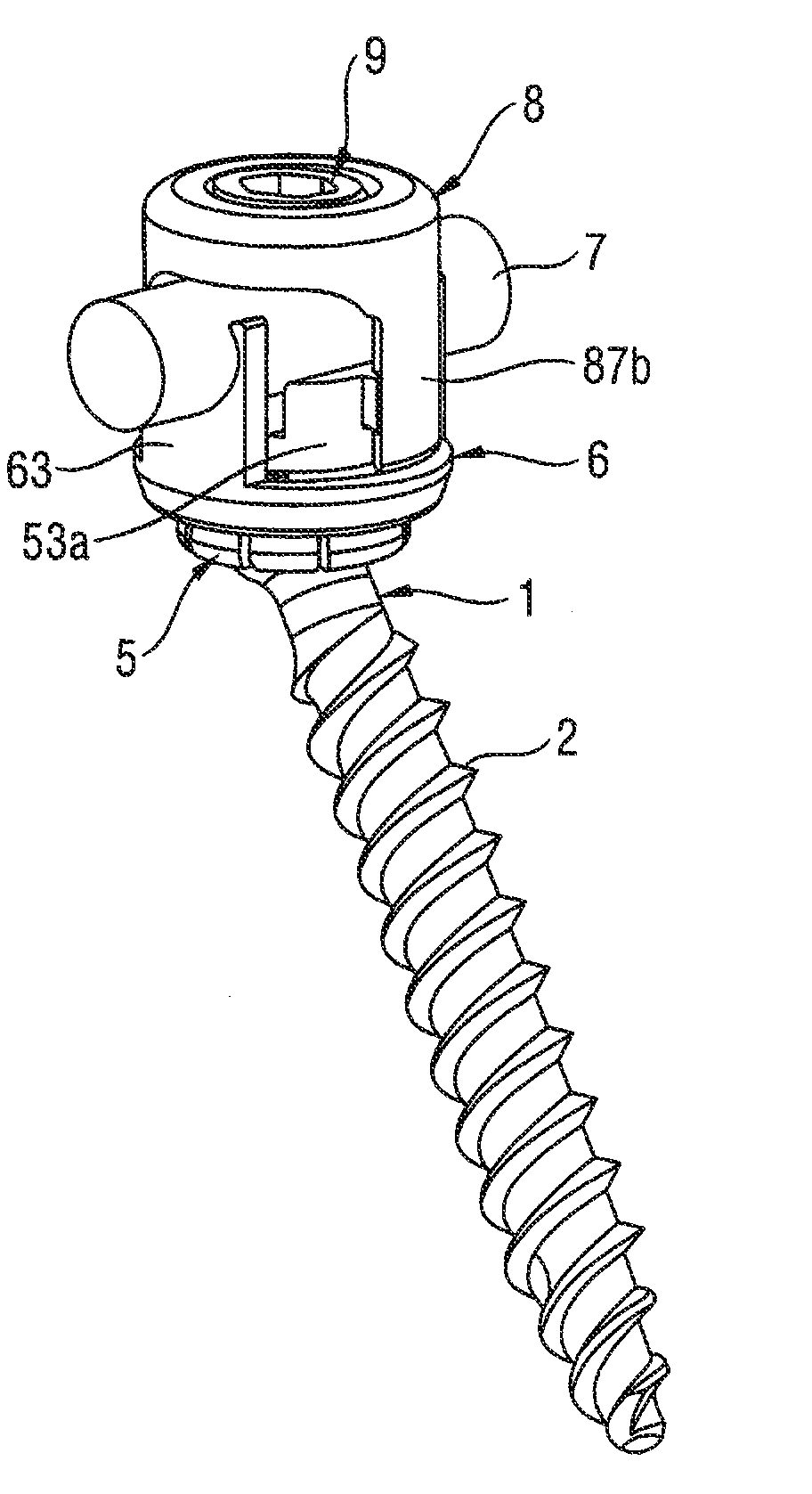
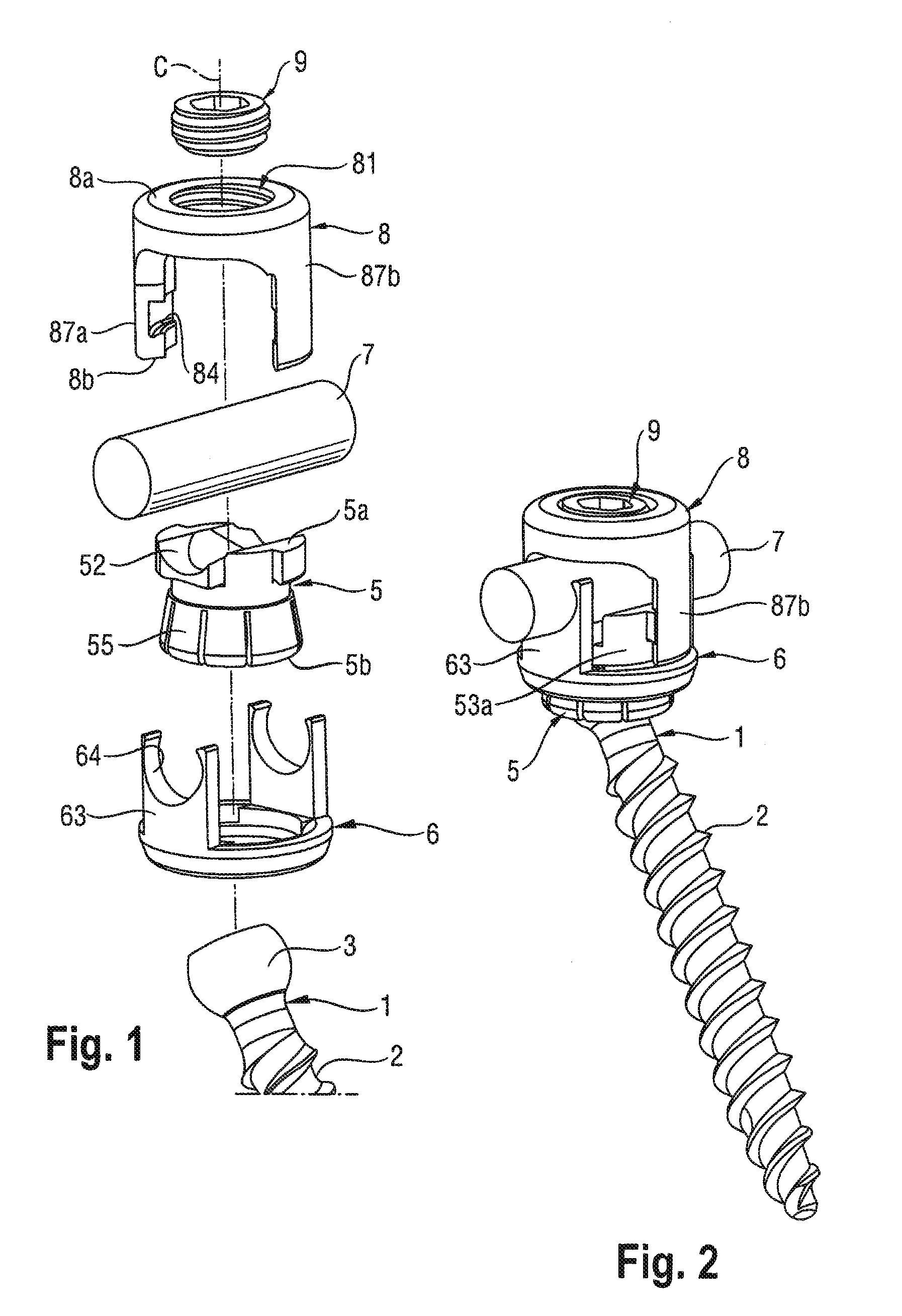
[0046]As shown in FIGS. 1 and 2, a polyaxial bone anchoring device according to a first embodiment includes a bone anchoring element 1 in the form of a bone screw having a shank 2 with a threaded portion and a spherical segment-shaped head 3. The head 3 has a recess 4 (see FIG. 16a) for engagement with a tool. The bone anchoring device further includes a head receiving part 5 for receiving the head 3 of the bone anchoring element 1, and a locking ring 6 for receiving a rod 7, for example, a spinal stabilization rod, and for connecting the rod 7 to the bone anchoring element 1. In addition, the bone anchoring device includes a cap 8 for securing the rod 7 and a locking element 9 in the form of a set screw for locking the rod 7 and the head 3 relative to the rest of the bone anchoring device.
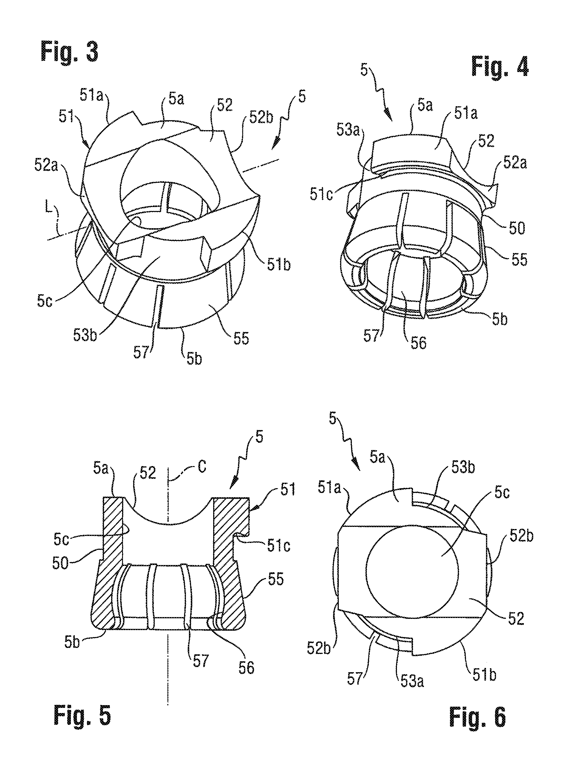
[0047]Referring in particular to FIGS. 3 to 6, the head receiving part 5 has a first end 5a and an opposite second end 5b, a central axis C and a coaxial through hole 5c. At the first end 5a, the ...
PUM
| Property | Measurement | Unit |
|---|---|---|
| Angle | aaaaa | aaaaa |
| Angle | aaaaa | aaaaa |
| Diameter | aaaaa | aaaaa |
Abstract
Description
Claims
Application Information
 - Generate Ideas
- Intellectual Property
- Life Sciences
- Materials
- Tech Scout
- Unparalleled Data Quality
- Higher Quality Content
- 60% Fewer Hallucinations
Browse by: Latest US Patents, China's latest patents, Technical Efficacy Thesaurus, Application Domain, Technology Topic, Popular Technical Reports.
© 2025 PatSnap. All rights reserved.Legal|Privacy policy|Modern Slavery Act Transparency Statement|Sitemap|About US| Contact US: help@patsnap.com