Exhaust system for two-stroke internal combustion engine

a two-stroke, exhaust system technology, applied in the direction of engines, mechanical equipment, machines/engines, etc., can solve the problems of inconvenient use, inefficient and inconsistent torque and power delivery, bulky exhaust systems, etc., to achieve more consistent torque and power, and improve fuel efficiency

Inactive Publication Date: 2013-05-23
SCHULTZ STEPHEN B
View PDF2 Cites 13 Cited by
  • Summary
  • Abstract
  • Description
  • Claims
  • Application Information

AI Technical Summary

Benefits of technology

[0007]The invention provides for constructing multiple exhaust expansion chambers of differing quantities and dimensions, each within one another, and which, when used in combination, allows for the combustible fuel / air mixture to be delivered in more optimal reflective pressure waves throughout the RPM range of the engine. The design of such exhaust pipes can be tuned for torque and power delivery according to the torque and power delivery goals of the engine's designer, while providing this advantage in a modest space. The system of utilizing two-stroke exhaust pipes with expansion chambers, one or more within another, can be economically constructed, will deliver better fuel efficiency and provide more consistently delivered torque and power throughout the RPM range, while producing these benefits in a more confined area than previously possible.

Problems solved by technology

It is inherently a problem of the two-stroke internal-combustion engine that it is inefficient and has inconsistent torque and power delivery.
Because of these problems, use of the relatively simple two-stroke engine has fallen from the favor of many vehicle manufacturers.
However, current designs that have achieved improved high levels of torque and power and / or efficiency result in bulky exhaust systems consisting of multiple, individual, stand-alone and ultimately-joined pipes with expansion chambers of differing dimensions, serving one piston, cylinder and one combustion chamber.
While these systems achieve attainable levels of torque, power and efficiency for a high performance exhaust system, the resulting structures do not meet the available space requirements of vehicle manufacturers.
Thus, it has proven difficult for a designer to achieve the maximum potentials of torque and power and efficiency throughout the entire RPM range of said engines while employing the torque and power-enhancing concept of an expansion chamber within the confines of a compact unit.
Although this structure improves somewhat the torque and efficiency without requiring additional space, it does not achieve the maximum potential possible with the use of expansion chambers in an exhaust system.

Method used


Image

  • Exhaust system for two-stroke internal combustion engine
  • Exhaust system for two-stroke internal combustion engine
  • Exhaust system for two-stroke internal combustion engine

Examples


Embodiment Construction

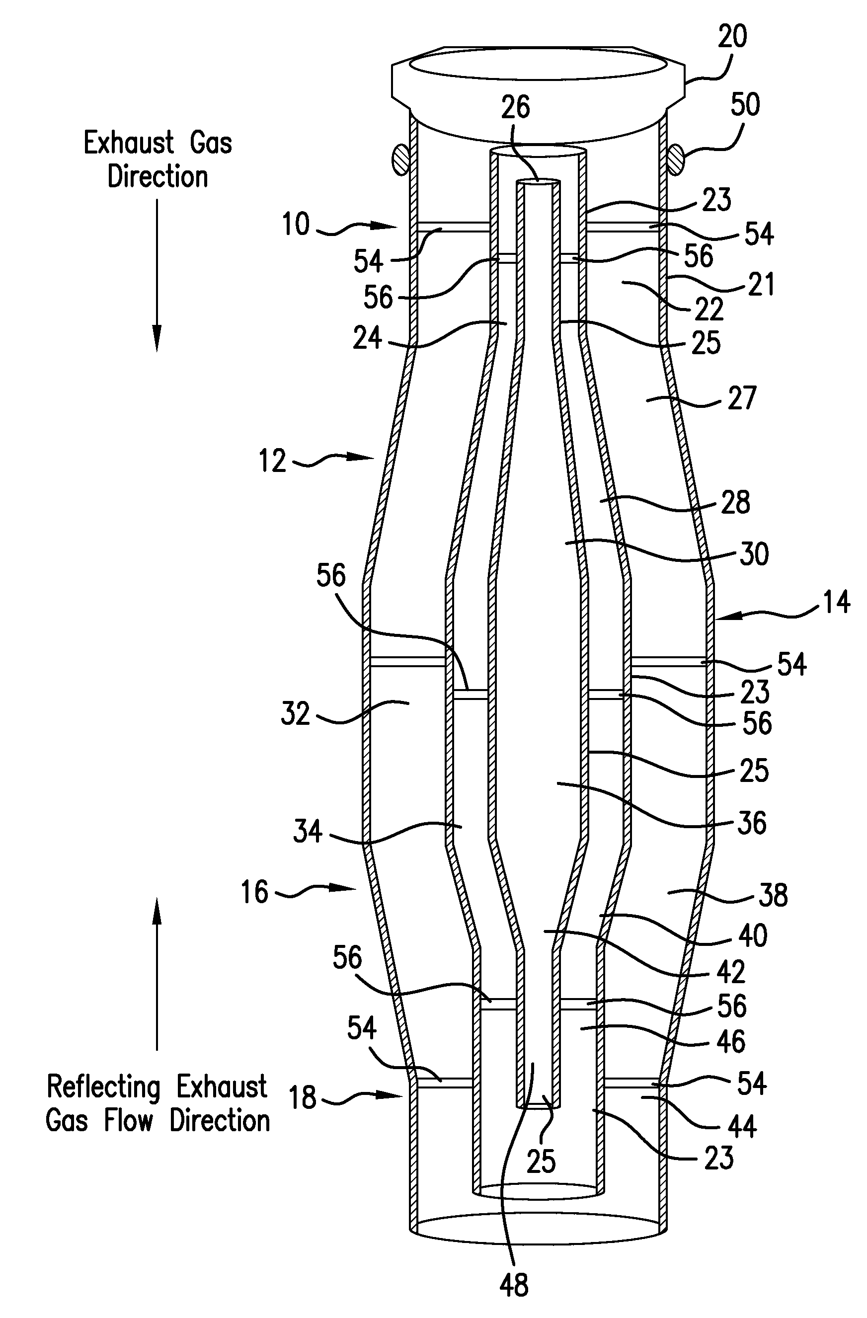
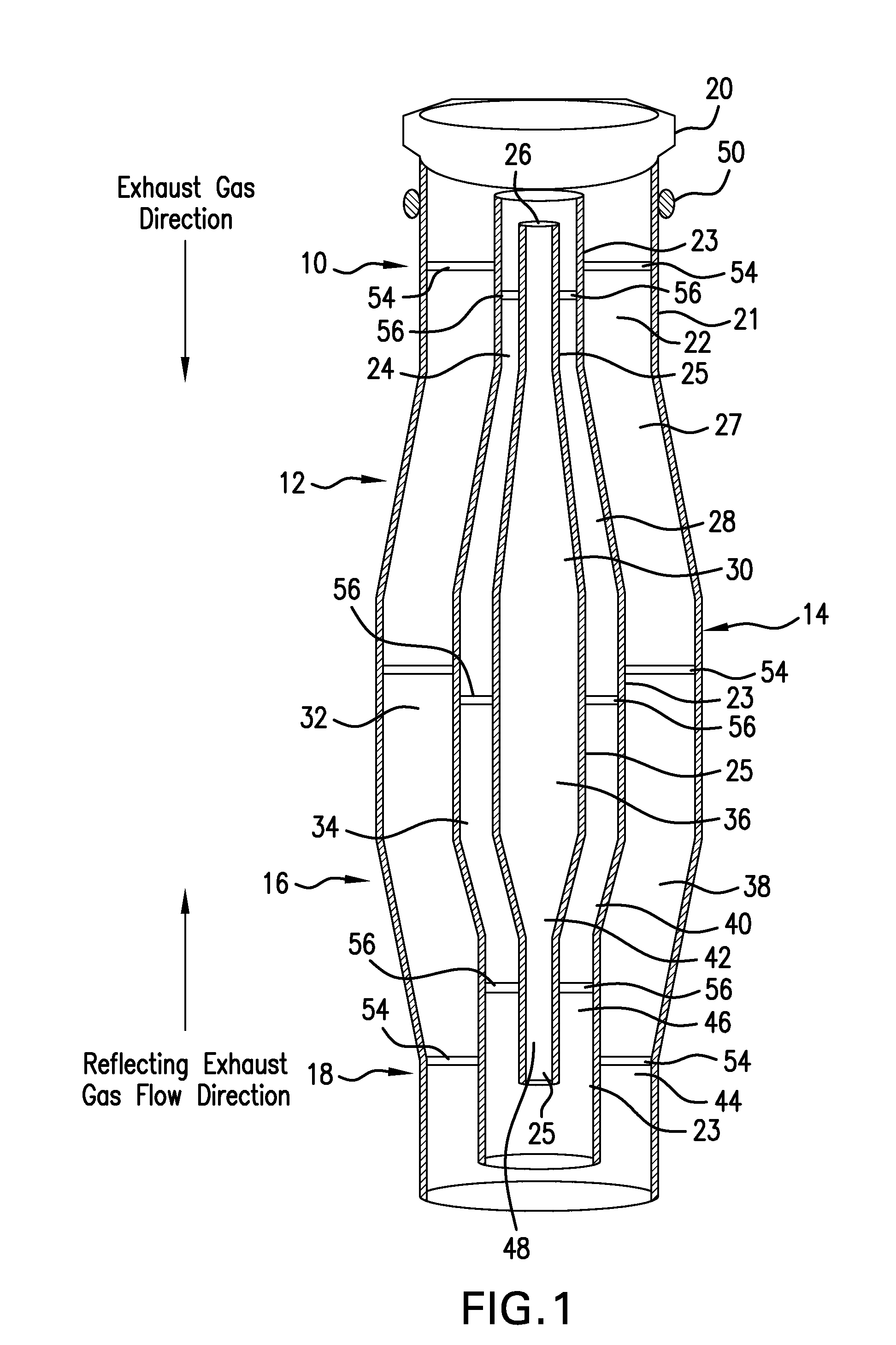
[0012]As previously stated, a main goal of a designer of exhaust systems for two-stroke internal combustion engines is to provide a design capable of reflecting certain beneficial pressure waves of exiting exhaust gases in a reverse direction, towards the engine's combustion chamber, where it will assist the entrapment of the next incoming quantity of the fresh mixture of fuel and air. As is known to those skilled in the art, this reverse pressure wave must arrive at an optimum time in the rotation cycle of the engine's crankshaft, as it relates to the rising piston and the piston's subsequent compression of the fresh charge of unburned air / fuel mixture. Such proper timing has been achieved in prior art designs through the use of an exhaust pipe incorporating a shape commonly known as the expansion chamber. The expansion chamber has multiple sections, and it greatly enhances the maximum torque and power output of earlier two-stroke engines which used a simple, straight-through exhau...


PUM


Abstract

An exhaust pipe for two-stroke, internal-combustion engines in which there are multiple exhaust expansion chambers, each within one another, used in combination, the multiple chambers allow for the combustible fuel / air mixture to be delivered in more optimal reflective pressure waves throughout the RPM range of the engine. By changing the number of the chambers, their size and shape, the design of the exhaust pipe can be tuned for torque and power while requiring a minimum of space.

Description

[0001]This application claims priority to U.S. Provisional Application 61 / 562,792 filed Nov. 22, 2011, the entirety of which is incorporated by reference herein.BACKGROUND OF THE INVENTION[0002]It is inherently a problem of the two-stroke internal-combustion engine that it is inefficient and has inconsistent torque and power delivery. It can be said that most if not all exhaust pipes for two-stroke engines produce a narrow power band width and are RPM related. Because of these problems, use of the relatively simple two-stroke engine has fallen from the favor of many vehicle manufacturers.[0003]The commonly used continuous-diameter exhaust pipe merely allows for the convenient exit of exhaust from a two-cycle engine. It is well known and accepted by those skilled in the art that the two stroke engine performance can be greatly improved with the assistance of a tuned exhaust system. If properly designed and constructed, a two-stroke exhaust pipe can improve the volumetric efficiency o...

Claims


Application Information

Patent Timeline
Patent Type & Authority Applications(United States)
IPC IPC(8): F01N3/00
CPCF01N3/00F01N13/08F01N2470/24F01N2470/20F02B27/04Y02T10/12
Inventor SCHULTZ, STEPHEN B.
Owner SCHULTZ STEPHEN B
Why Eureka
Try Eureka