
Down-Flow Direct Contact Cooler

Inactive Publication Date: 2013-05-23
FLUOR TECH CORP
View PDF11 Cites 1 Cited by
  • Summary
  • Abstract
  • Description
  • Claims
  • Application Information

AI Technical Summary

Benefits of technology

The patent is about a system that cools down a stream of gas using a gas conditioning system. The gas is first heated up in a process and then cooled down in a second stage using a colder second gas. This process helps to remove water from the gas. This system can be used in power plants or other industrial facilities to treat the exhaust gases from combustion.

Problems solved by technology

Although down-flow DCCs are discussed in U.S. Pat. Nos. 4,073,634, 4,168,150, and 4,252,553 to Pircon, et al., such coolers are (1) impractical because of the impact of flue gas impurities such as SO2 and other acid gases on the coolers and downstream components, and (2) inefficient because of the co-current heat exchange.

Method used


Image

  • Down-Flow Direct Contact Cooler
  • Down-Flow Direct Contact Cooler
  • Down-Flow Direct Contact Cooler

Examples


Embodiment Construction

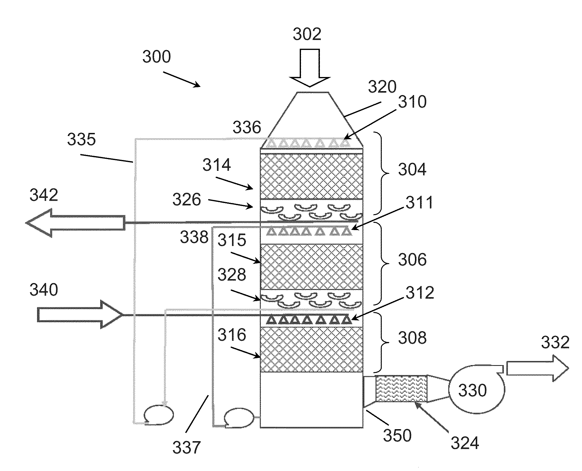
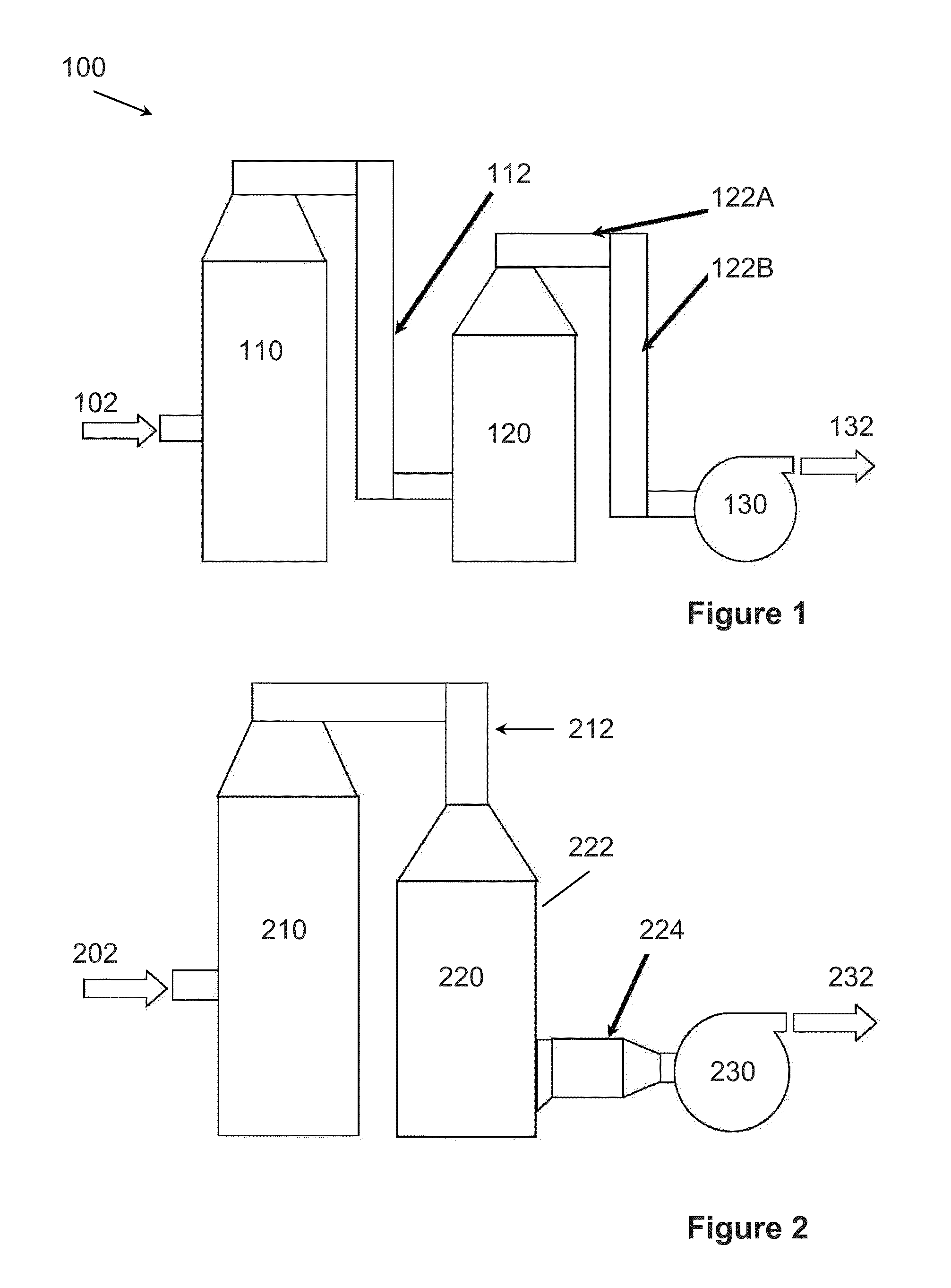
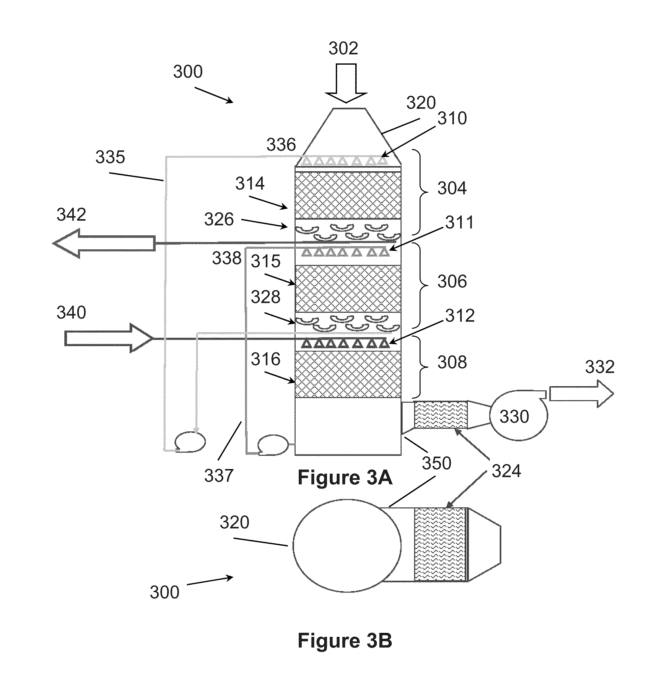
[0016]One should appreciate that the disclosed techniques provide many advantageous technical effects including the elimination of costly ductwork, which reduces the cost, space required, and pressure drop of the system. The inventive subject matter discussed herein could be applied to almost all post-combustion CO2 capture processes including, but not limited to, processes that are both commercially-available or under current or future development. This could include, for example, applications in power, pulp and paper, mining, refining, steel and other industries.

[0017]The following discussion provides many example embodiments of the inventive subject matter. Although each embodiment represents a single combination of inventive elements, the inventive subject matter is considered to include all possible combinations of the disclosed elements. Thus if one embodiment comprises elements A, B, and C, and a second embodiment comprises elements B and D, then the inventive subject matter ...


PUM


Abstract

Systems and methods are contemplated for down-flow cooling of a feed gas. Contemplated systems can include a housing having an inlet conduit disposed within an upper portion and configured to receive a first stream. First and second stages can be disposed within the housing, with the first stage disposed upstream of the second stage and having a first cooling stream, and the second stage having a second cooling stream that is colder than the first cooling stream. The housing can be configured such that the first stream is cooled by down-flow heat exchange with the first and second cooling streams to produce a conditioned stream depleted of at least a portion of water condensed from the feed gas.

Description

FIELD OF THE INVENTION[0001]The field of the invention is gas conditioning systems.BACKGROUND[0002]In direct contact coolers (DCCs) such as the Econamine FG PlusSM plant at Bellingham, Mass. and those described in U.S. Pat. No. 2,715,948 to Lewis, et al., a gas typically enters a side of the DCC vessel, turns 90 degrees, passes through irrigated packing, and exits through a top of the DCC vessel. When a DCC is coupled downstream of another gas cleaning system such as a flue gas desulfurization (FGD) system (see FIG. 1), complex ductwork arrangement is typically required because the product gas exits the top of the FGD and is then directed to the bottom of an adjacent DCC where the gas then flows to the top of the DCC and back down to the ground into a blower or booster fan.[0003]Although down-flow DCCs are discussed in U.S. Pat. Nos. 4,073,634, 4,168,150, and 4,252,553 to Pircon, et al., such coolers are (1) impractical because of the impact of flue gas impurities such as SO2 and ot...

Claims


Application Information

Patent Timeline
IPC IPC(8): B01D8/00
CPCB01D8/00B01D5/003B01D53/002B01D53/1431
Inventor JOHNSON, DENNIS W.
Owner FLUOR TECH CORP
Features
  • Generate Ideas
  • Intellectual Property
  • Life Sciences
  • Materials
  • Tech Scout
  • Unparalleled Data Quality
  • Higher Quality Content
  • 60% Fewer Hallucinations
Learn More