Burn-in test apparatus with function of energy recycling

a test apparatus and energy recycling technology, applied in the field of burnin test apparatus, can solve the problems of increasing cost, affecting goodwill, unstable testing current, etc., and achieve the effects of reducing manufacturing cost, high energy recycling ratio, and simplifying control and circui

Inactive Publication Date: 2013-05-23
NAT TAIWAN UNIV OF SCI & TECH
View PDF2 Cites 13 Cited by
  • Summary
  • Abstract
  • Description
  • Claims
  • Application Information

AI Technical Summary

Benefits of technology

[0017]The invention possesses the following advantages: (1) single stage structure, which simplifies the controlling and circuit, and reduces the cost to manufacture; (2) high ratio of energy recycling, which is verified saving about 70% energy by the experiments; (3) recycling energy in direct current, which is not required to be connected to the mains supply, and thus can neglect the standard to connect to the mains supply; and (4) reducing the testing duration because the invention can test multiple power converters simultaneously.

Problems solved by technology

If the defect products cannot be filtered out before shipping the products, it may affect the goodwill and increase the cost.
The passive electrical load mainly includes the resistance load boxes, which are sensitive to the output voltage of the power converters to be tested, the temperature coefficients of the resistance and no-feedback control, and thus the testing current are not stable.
However, both of the passive electrical load and active electrical load need the resistance load boxes, which consume the electricity and result in heat.
Thus, fans are required to cool down the resistance load boxes, and make the testing apparatus huge and consume additional power.
That is, the burn-in test to improve the reliability and quality of products consumes lots of power and increase the released carbon.
Therefore, the traditional burn-in test violates the environmental concepts of low carbon footprint and energy-saving, and increases the cost to produce the products.
However, the current burn-in apparatuses for the AC / DC power converters mainly feed the alternating current to the mains supply, and need one more stage of DC / AC power converters, which are complicated and can recycle less electricity.

Method used


Image

  • Burn-in test apparatus with function of energy recycling
  • Burn-in test apparatus with function of energy recycling
  • Burn-in test apparatus with function of energy recycling

Examples


Embodiment Construction

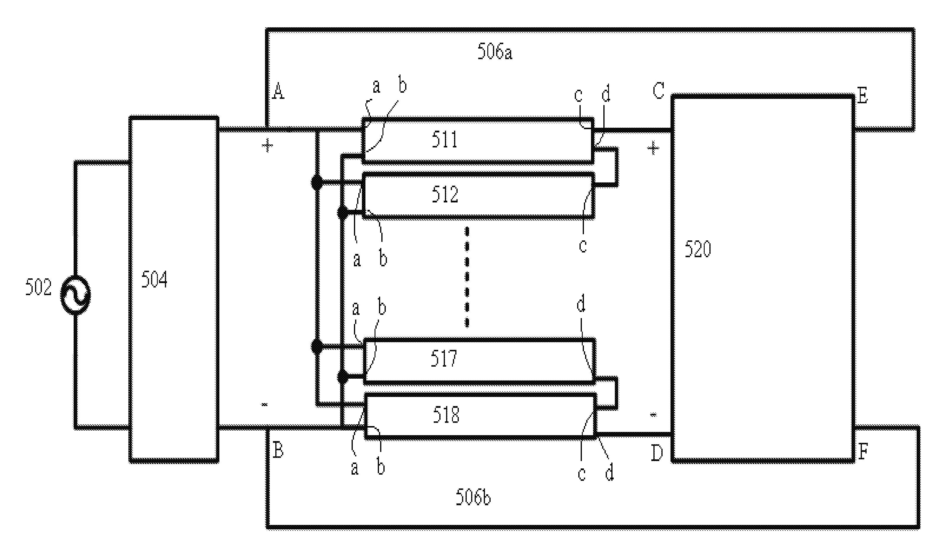
[0024]FIG. 5 illustrates a structure of a burn-in test apparatus on the basis of an embodiment of the invention. FIG. 5 shows a burn-in test apparatus including an AC / DC power converter 504 and an active electrical load 520, wherein the AC / DC power converter 504 can be a full-bridge rectifier, and the active electrical load 520 can be a DC / DC power converter.

[0025]AC / DC power converter 504 mainly employs a full-bridge rectifier to convert the alternating current of the AC power source 502 of the mains supply to direct current, which is then supplied to the input ends (a, b) of one or more power converters (511˜518). The voltage of the current into the one or more power converters (511˜518) is regulated by the input capacitors inside the one or more power converters (511˜518).

[0026]In an embodiment of the invention, to test multiple power converters (511˜518) and reduce the test duration, the input ends (a, b) of power converter (511˜518) are connected in parallel and the output ends...


PUM


Abstract

A new electrical recycling apparatus for AC/DC power converter is provided to recycle the electricity in direct current to the input ends of the power converter to be tested to save a stage of power converter and avoid the complicated standard and requirement that feed the electricity to the mains supply.

Description

CROSS-REFERENCE TO RELATED APPLICATION[0001]This present application claims priority to TAIWAN Patent application Ser. No. 100142430, filed on Nov. 18, 2011, which is herein incorporated by reference in its integrity.TECHNICAL FIELD[0002]The invention is relevant to a burn-in test apparatus, especially which can test the power converter, and recycle energy.DESCRIPTION OF THE RELATED ART[0003]In the competition of the business, the manufactures have to not only meet the industrial standard but also guarantee the reliability and quality. If the defect products cannot be filtered out before shipping the products, it may affect the goodwill and increase the cost. Therefore, the manufactures of the power converter will do the burn-in test before delivering the products.[0004]Besides keeping the quality of the products, lots of countries and enterprises promote the carbon footprint labels, which are required to be provided by manufactures and their suppliers. Therefore, besides the advanc...

Claims


Application Information

Patent Timeline
Patent Type & Authority Applications(United States)
IPC IPC(8): G01R31/10
CPCG01R31/40
Inventor CHANG, HONG-CHANKUO, CHENG-CHIENHUANGLI, CHIEN
Owner NAT TAIWAN UNIV OF SCI & TECH
Why Eureka
Try Eureka