
Antenna Apparatus, Antenna System, and Antenna Electrical Tilting Method

a technology of antenna apparatus and antenna system, applied in the field of communication, can solve the problems of incorrect antenna configuration, network failure to be optimized correctly, incorrect information on the maintenance platform of the base station, etc., and achieve the effect of reducing the human error rate, reducing the installation cost, and improving the accuracy of project implementation

Active Publication Date: 2013-05-23
HUAWEI TECH CO LTD
View PDF13 Cites 23 Cited by
  • Summary
  • Abstract
  • Description
  • Claims
  • Application Information

AI Technical Summary

Benefits of technology

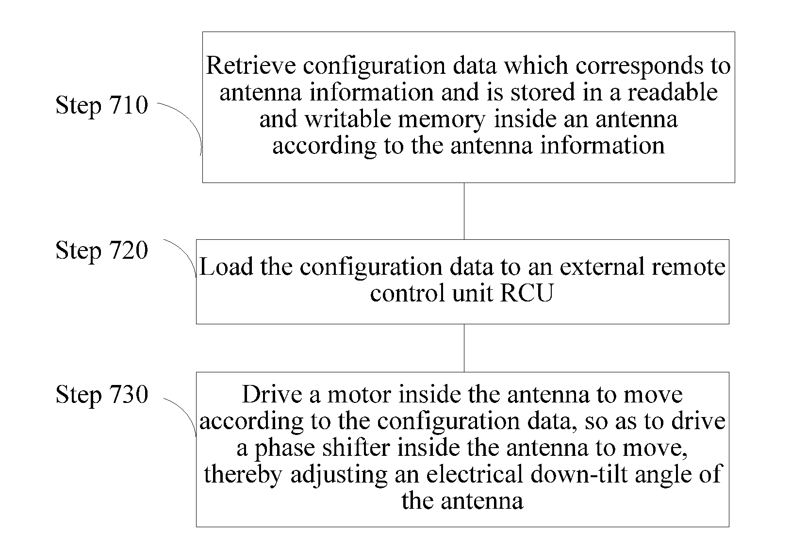
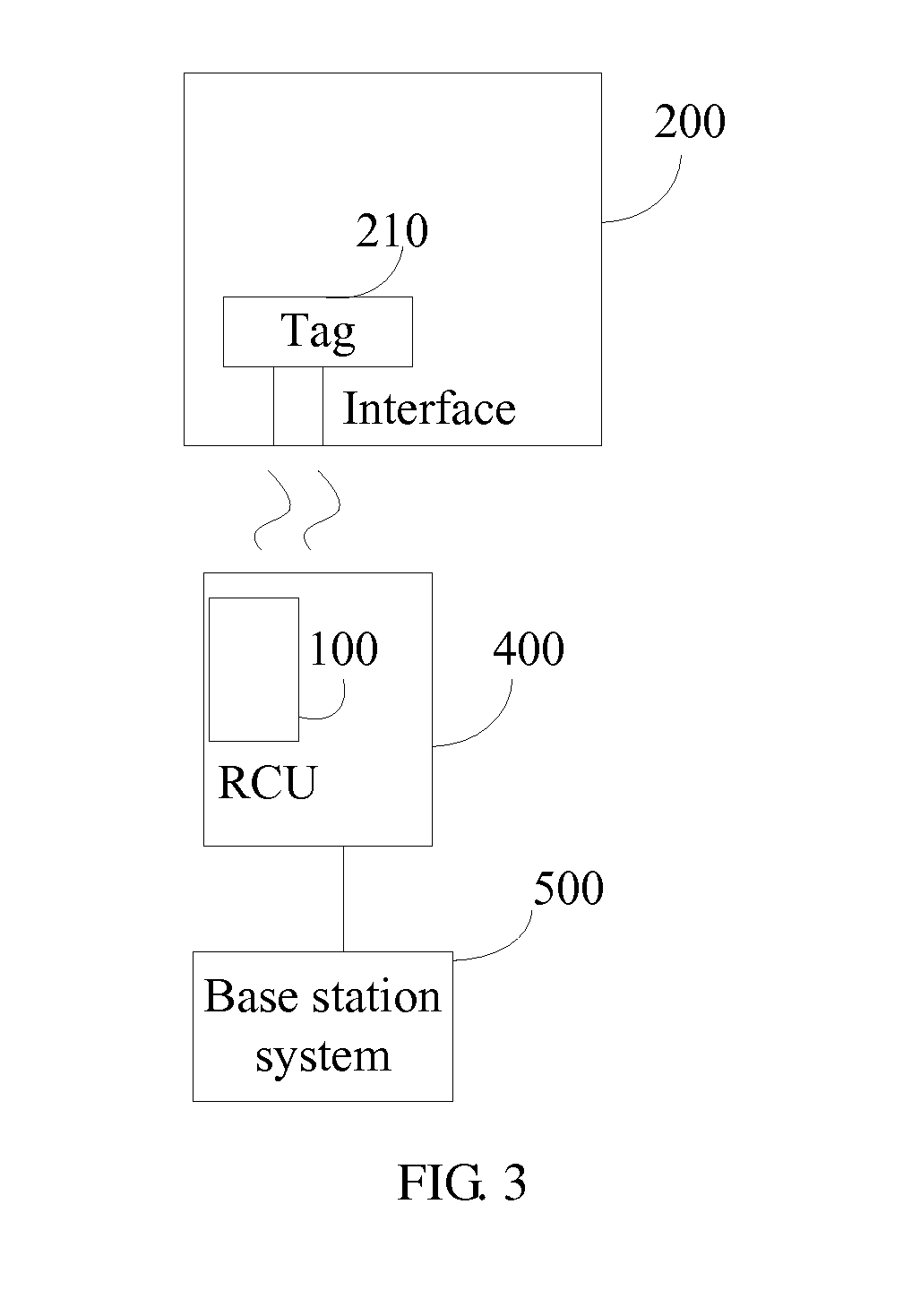
The present invention provides a solution to improve the accuracy and efficiency of antenna installation and maintenance. By incorporating a memory within the antenna, external devices can conveniently call the memory to configure the antenna and remotely control its electrical down-tilt angle. This reduces human error, lowers installation costs, and facilitates maintenance.

Problems solved by technology

These cases result in incorrect information on the base station maintenance platform and incorrect configuration for the antennas.
Consequently, the network fails to be optimized correctly.
To correct the information, the installation personnel need to mount over the tower and read and write down the information again, causing repeated operations which wastes manpower and resources.
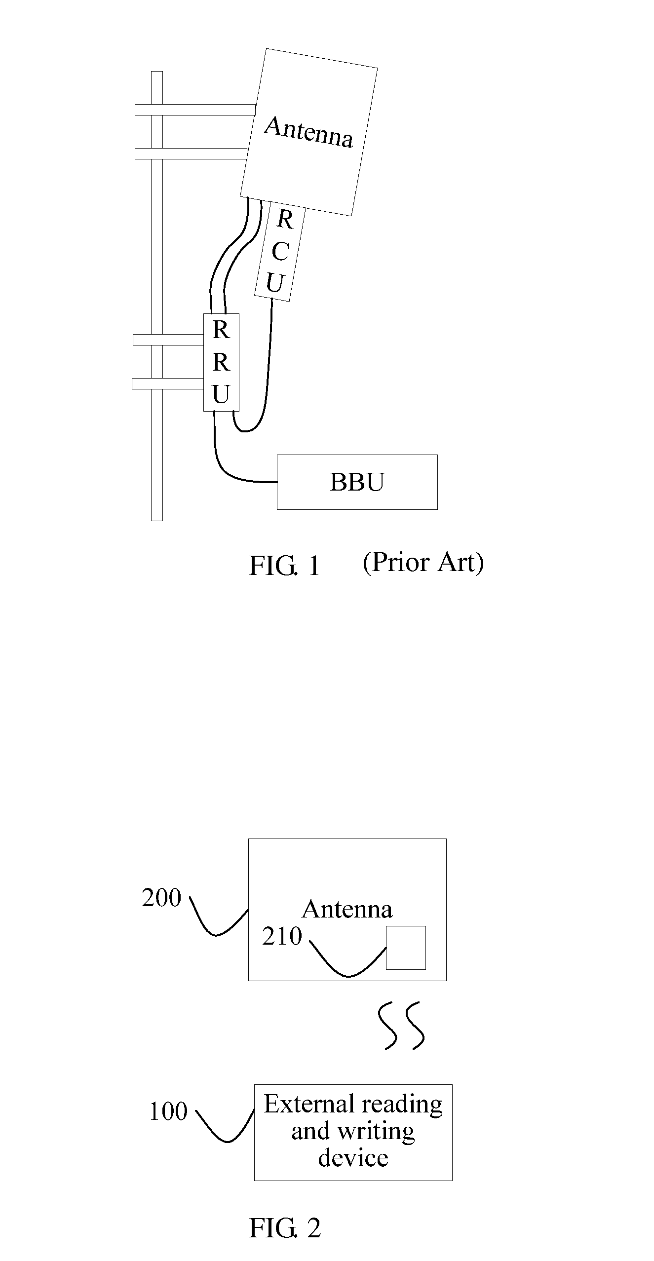
However, this causes a problem that the RCU occupies the internal volume of the antenna, resulting in a large antenna volume.
And if the RCU board and motor are built in the antenna, if the board or motor is faulty, it is difficult to dismantle them, and even if they are dismantled, the antenna is damaged and cannot be maintained.

Method used


Image

  • Antenna Apparatus, Antenna System, and Antenna Electrical Tilting Method
  • Antenna Apparatus, Antenna System, and Antenna Electrical Tilting Method
  • Antenna Apparatus, Antenna System, and Antenna Electrical Tilting Method

Examples


Embodiment Construction

[0019]To make the objective, technical solutions, and advantages of the present invention clearer, the present invention is described below in further detail with reference to specific embodiments and relevant accompanying drawings.

[0020]An embodiment of the present invention provides an antenna apparatus, configured to be used in conjunction with an RCU (remote control unit, e.g., external remote control unit), and including a motor, a phase shifter, and a readable and writable memory.

[0021]The readable and writable memory is configured to store configuration data of an antenna and antenna information corresponding to the configuration data, where when the configuration data is loaded to the RCU, the RCU is enabled to drive the motor to move according to the configuration data. The antenna information optionally includes one or more of all antenna models, antenna frequency bands, and antenna serial numbers, so that the RCU can obtain the configuration data of the corresponding ante...


PUM


Abstract

Embodiments of the present invention provide an antenna apparatus, a system, and an adjusting method. The antenna apparatus is configured to be used in conjunction with an RCU (remote control unit, external remote control unit). The antenna apparatus includes a readable and writable memory and a motor. The readable and writable memory is configured to store configuration data of an antenna and antenna information corresponding to the configuration data, where the configuration data is used to control the RCU to drive the motor to move, so as to adjust an electrical down-tilt angle of the antenna.

Description

[0001]This application is a continuation of co-pending International Application No. PCT / CN2011 / 078991, filed Aug. 26, 2011, which claims priority to Chinese Patent Application No. 201010555649.1, filed Nov. 23, 2010, both of which applications are incorporated herein by reference.TECHNICAL FIELD[0002]The present invention relates generally to the field of communications, and in particular embodiments, to an antenna apparatus, an antenna system, and an antenna electrical tilting method in a base station system.BACKGROUND[0003]Electrical tilting antennas have become the mainstream in mobile communication systems. An electrical tilting antenna refers to a mobile antenna for which the down-tilt angle is adjusted electrically. A maintenance system located in a base station adjusts the electrical down-tilt angle of the antenna for network optimization.[0004]FIG. 1 is a schematic diagram of a base station system including an electrical tilting antenna, which includes an antenna tower, an ...

Claims


Application Information

Patent Timeline
Patent Type & Authority Applications(United States)
IPC IPC(8): H01Q3/00
CPCH01Q1/246H01Q3/005H01Q3/34H04W16/28H01Q3/00H01Q3/06
Inventor ZHANG, TINGTINGWANG, JISONGXIE, SHOUBOPEI, SHUBAO
Owner HUAWEI TECH CO LTD
Learn More