3D image pickup optical apparatus and 3D image pickup apparatus
a technology of applied in the field of 3d image pickup optical apparatus and 3d image pickup apparatus, to achieve the effect of saving time and effort, small and simple structur
- Summary
- Abstract
- Description
- Claims
- Application Information
AI Technical Summary
Benefits of technology
Problems solved by technology
Method used
Image
Examples
embodiment 1
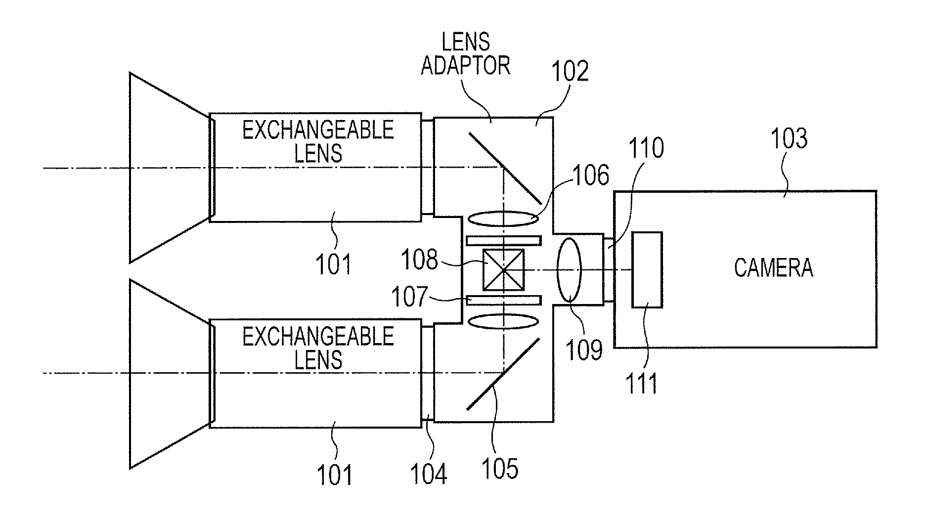
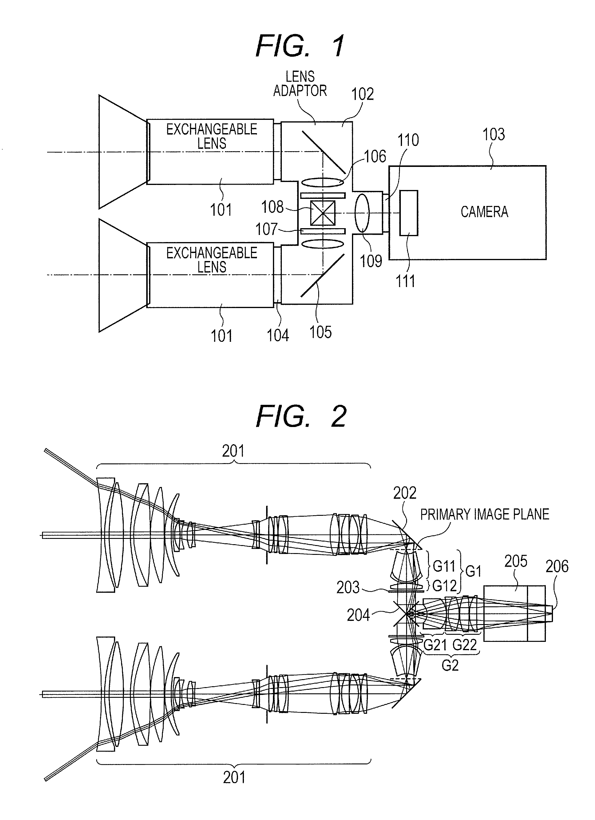
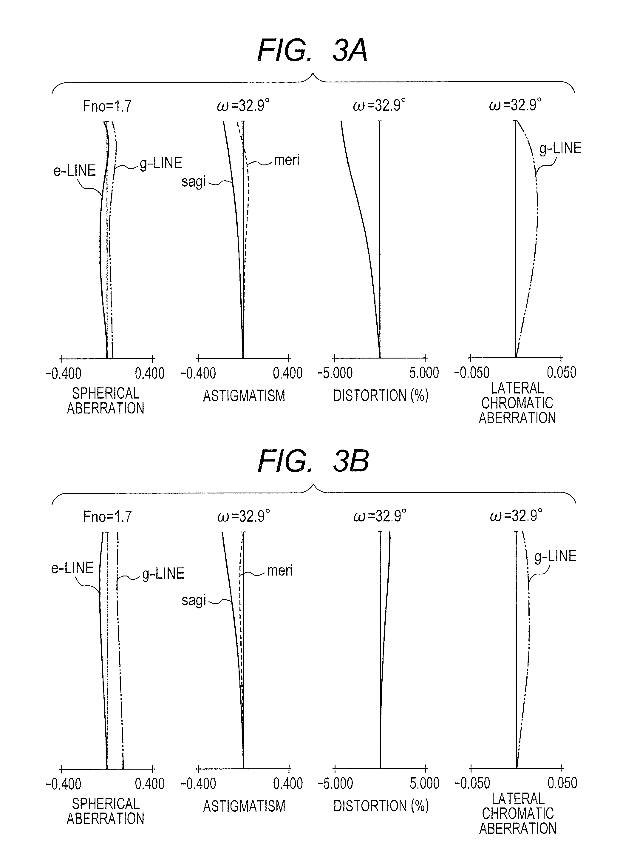
[0026]With reference to FIG. 1, a schematic structure of a 3D image pickup apparatus according to Embodiment 1 of the present invention is hereinafter described.
[0027]The 3D image pickup apparatus of the present invention for taking two subject images having a disparity includes two lens apparatus and one image pickup apparatus, in which the lens apparatus as exchangeable lenses can be directly connected to the image pickup apparatus for taking the subject images, and an optical apparatus (a lens adapter) disposed between the exchangeable lens and the image pickup apparatus. The 3D image pickup apparatus includes left and right (two) exchangeable lenses 101 (a first lens apparatus and a second lens apparatus) for taking subject images having a disparity, a lens adapter 102 as an optical apparatus for combining the left and right images, and an image pickup camera 103 of a lens exchangeable type. Attaching members 104 as units for attaching the exchangeable lenses in a detachable man...
embodiment 2
[0073]Embodiment 2 of the present invention is hereinafter described.
[0074]In Embodiment 2, the distance D between the optical axes of the left and right exchangeable lenses is 200 mm, which is larger than that in Embodiment 1. Therefore, the stereoscopic effect is more exaggerated compared with human sense. Other structures of the apparatus including the exchangeable lenses are exactly the same as those in Embodiment 1.
[0075]FIG. 4 is an optical path diagram of a lens system according to Embodiment 2 of the present invention (Numerical Embodiment 2) when focusing on an object at infinity at the wide angle end. FIG. 5 is a longitudinal aberration diagram when focusing on an object at a subject distance of 3 meters at the wide angle end according to Embodiment 2. Note that, because the exchangeable lenses are exactly the same as those of Embodiment 1, the aberration diagram at the telephoto end is omitted.
[0076]In Numerical Embodiment 2 corresponding to Embodiment 2, the focal length...
embodiment 3
[0077]Embodiment 3 of the present invention is hereinafter described.
[0078]In Embodiment 3, the distance D between the optical axes between the left and right exchangeable lenses is 100 mm, which is smaller than that in Embodiment 1. Therefore, the stereoscopic effect closer to the human sense can be obtained. Other structures of the apparatus including the exchangeable lenses are exactly the same as those in Embodiment 1.
[0079]FIG. 6 is an optical path diagram of a lens system according to Embodiment 3 of the present invention (Numerical Embodiment 3) when focusing on an object at infinity at the wide angle end. FIG. 7 is a longitudinal aberration diagram when focusing on an object at a subject distance of 3 meters at the wide angle end according to Embodiment 3. Note that, because the exchangeable lenses are exactly the same as those of Embodiment 1, the aberration diagram at the telephoto end is omitted.
[0080]In Numerical Embodiment 3 corresponding to Embodiment 3, the focal leng...
PUM
 Abstract
Description
Claims
Application Information
 - R&D
- Intellectual Property
- Life Sciences
- Materials
- Tech Scout
- Unparalleled Data Quality
- Higher Quality Content
- 60% Fewer Hallucinations
Browse by: Latest US Patents, China's latest patents, Technical Efficacy Thesaurus, Application Domain, Technology Topic, Popular Technical Reports.
© 2025 PatSnap. All rights reserved.Legal|Privacy policy|Modern Slavery Act Transparency Statement|Sitemap|About US| Contact US: help@patsnap.com


