Bending sensor
a technology of bending sensor and bending angle, which is applied in the direction of force measurement, instruments, using mechanical means, etc., can solve problems such as reducing electrical resistance, and achieve the effect of limited sensitivity variation and high sensitivity
- Summary
- Abstract
- Description
- Claims
- Application Information
AI Technical Summary
Benefits of technology
Problems solved by technology
Method used
Image
Examples
first embodiment
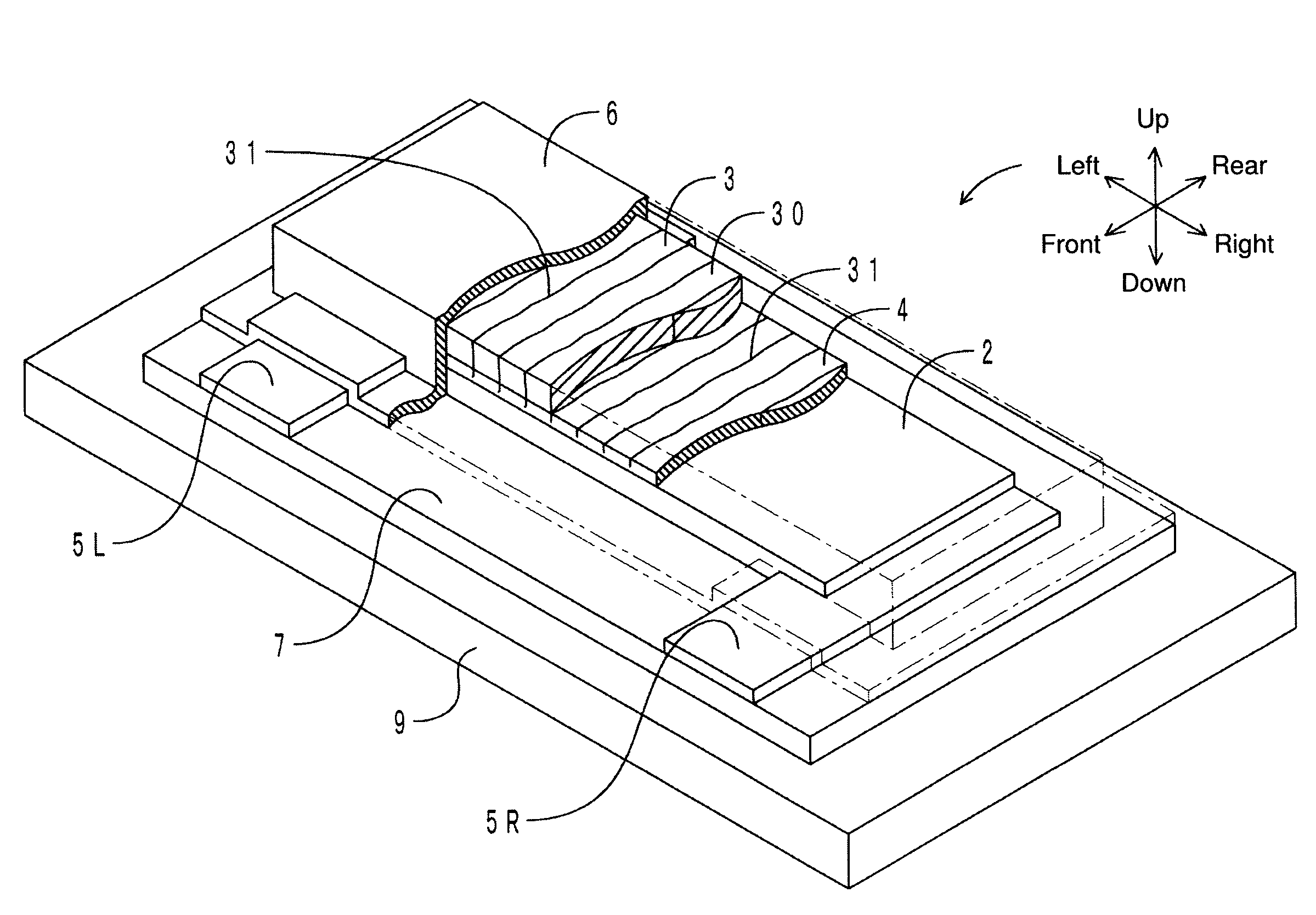
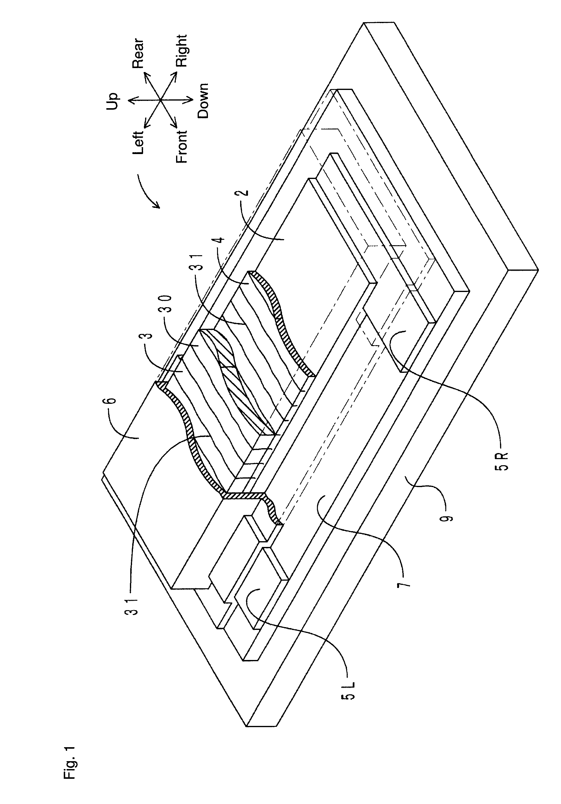
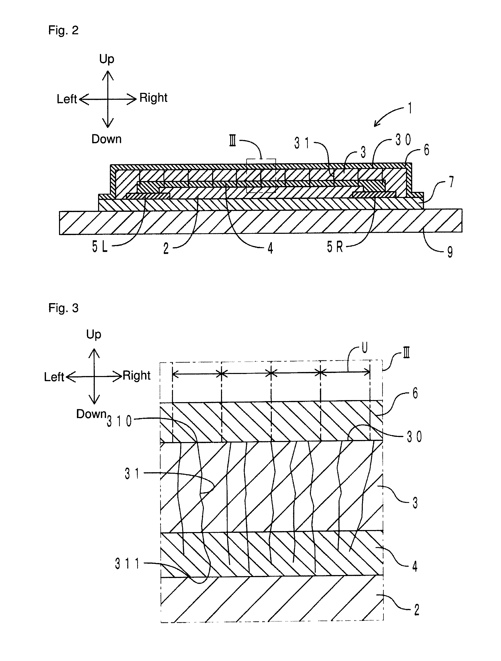
[0067]For ease of description, a length in a left-right direction is decreased and a length in an up-down direction (thickness) is increased relative to actual dimensions of a bending sensor in the drawings referred to below. In the drawings, the left-right direction corresponds to a “placement direction of a plurality of electrode portions” of the present invention. A front-rear direction corresponds to a “direction orthogonal to the placement direction of the plurality of electrode portions” of the present invention. The up-down direction corresponds to a “laminating direction” of the present invention. An upper side corresponds to a “load output side” of the present invention. A lower side corresponds to a “load input side” of the present invention.
[0068]FIG. 1 is a transparent perspective view of the bending sensor according to the present embodiment. FIG. 2 is a cross-sectional view in the left-right direction of the bending sensor. FIG. 3 is an enlarged view of a portion in a ...
second embodiment
[0116]A bending sensor according to the present embodiment is different from the bending sensor of the first embodiment only in a shape of a high resistance layer. Only the difference is described herein. FIG. 9 is a transparent perspective view of the bending sensor according to the present embodiment. Components corresponding to those in FIG. 1 are denoted with the same reference numerals.
[0117]With reference to FIG. 9, a high resistance layer 2 of a bending sensor 1 is disposed in an S shape between a pair of electrode portions 5L and 5R. Specifically, the high resistance layer 2 has a front portion 2a, a central portion 2b, and a rear portion 2c, which are continuous and formed into an S shape. The front portion 2a, the central portion 2b, and the rear portion 2c each extend in the left-right direction. A left end of the front portion 2a is connected to the electrode portion 5L. A right end of the rear portion 2c is connected to the electrode portion 5R.
[0118]With reference to F...
third embodiment
[0120]A bending sensor according to the present embodiment is different from the bending sensor of the first embodiment in that a high resistance layer is disposed on a surface on a load input side of a base material. Only the difference is described herein. FIG. 10 is a cross-sectional view in the left-right direction of the bending sensor according to the present embodiment. Components corresponding to those in FIG. 2 are denoted with the same reference numerals.
[0121]With reference to FIG. 10, a high resistance layer 2 is printed on a lower surface of a base material 7. The base material 7 is included in a concept of a “reinforcement layer” of the present invention. A pair of electrode portions 50L and 50R is disposed at each of a left and right end (each longitudinal end) of the high resistance layer 2. The high resistance layer 2 and the pair of electrode portions 50L and 50R are covered by a covering layer 90 from below. On an upper surface of the base material 7, an insulatin...
PUM
| Property | Measurement | Unit |
|---|---|---|
| resistance | aaaaa | aaaaa |
| length | aaaaa | aaaaa |
| length | aaaaa | aaaaa |
Abstract
Description
Claims
Application Information
 - R&D
- Intellectual Property
- Life Sciences
- Materials
- Tech Scout
- Unparalleled Data Quality
- Higher Quality Content
- 60% Fewer Hallucinations
Browse by: Latest US Patents, China's latest patents, Technical Efficacy Thesaurus, Application Domain, Technology Topic, Popular Technical Reports.
© 2025 PatSnap. All rights reserved.Legal|Privacy policy|Modern Slavery Act Transparency Statement|Sitemap|About US| Contact US: help@patsnap.com


