Non-catalytic biomass fuel burner and method

a biomass burner and non-catalytic technology, applied in the field of biomass burners, can solve the problems of reducing the expected lifetime of catalytic stoves to two years, requiring replacement plates for hundreds of dollars to purchase today, and being difficult to maintain catalytic stoves

Inactive Publication Date: 2013-05-30
LASKOWSKI SCOTT +3
View PDF4 Cites 24 Cited by
  • Summary
  • Abstract
  • Description
  • Claims
  • Application Information

AI Technical Summary

Benefits of technology

[0009]According to a broad aspect of the present invention, a non-catalytic biomass burner is provided comprising: a combustion chamber for burning a fuel to produce an exhaust gas, wherein the combustion chamber has a cylindrical interior shape with the sides of the combustion chamber enclosed by a side wall; one or more air inlets spanning the side wall of the combustion chamber to allow air to enter the combustion chamber from the outside of the combustion chamber through the one or more air inlets; a flue pipe connected at its proximal end to the top of the combustion chamber, the flue pipe being configured to receive the exhaust gas from the combustion chamber through a flue opening, a heat exchanger for transfe

Problems solved by technology

Most complaints about catalytic stoves relate to maintaining or replacing the catalytic combustor plate.
Catalytic stoves are generally thought to be harder to maintain as the catalytic plate requires some amount of care with cleaning and replacing.
Improper use or burning can reduce this expected lifetime to two years.
As for expense, such replacement plate

Method used


Image

  • Non-catalytic biomass fuel burner and method
  • Non-catalytic biomass fuel burner and method
  • Non-catalytic biomass fuel burner and method

Examples


Embodiment Construction

[0031]The detailed description set forth below in connection with the appended drawings is intended as a description of various embodiments of the invention and is not intended to represent the only embodiments of the invention or the only manner in which the invention may be practiced. The detailed description includes some specific details for the purpose of providing an understanding of the invention. However, it will be apparent to those skilled in the art that these details may be provided as merely illustrative examples and / or optional features of the present invention. Some well-known structures and components may also be depicted in block diagram form to avoid obscuring concepts of the present invention.

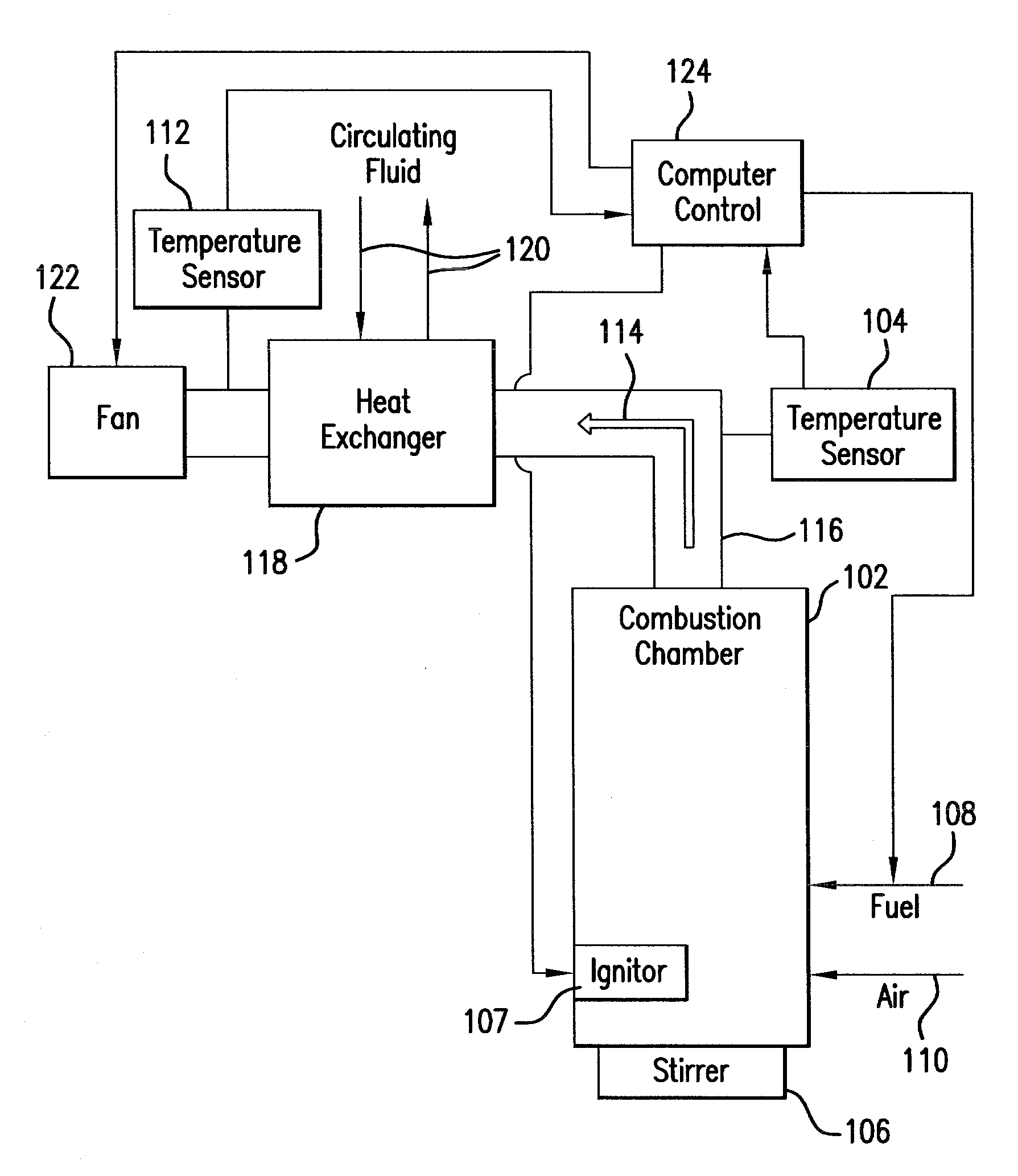
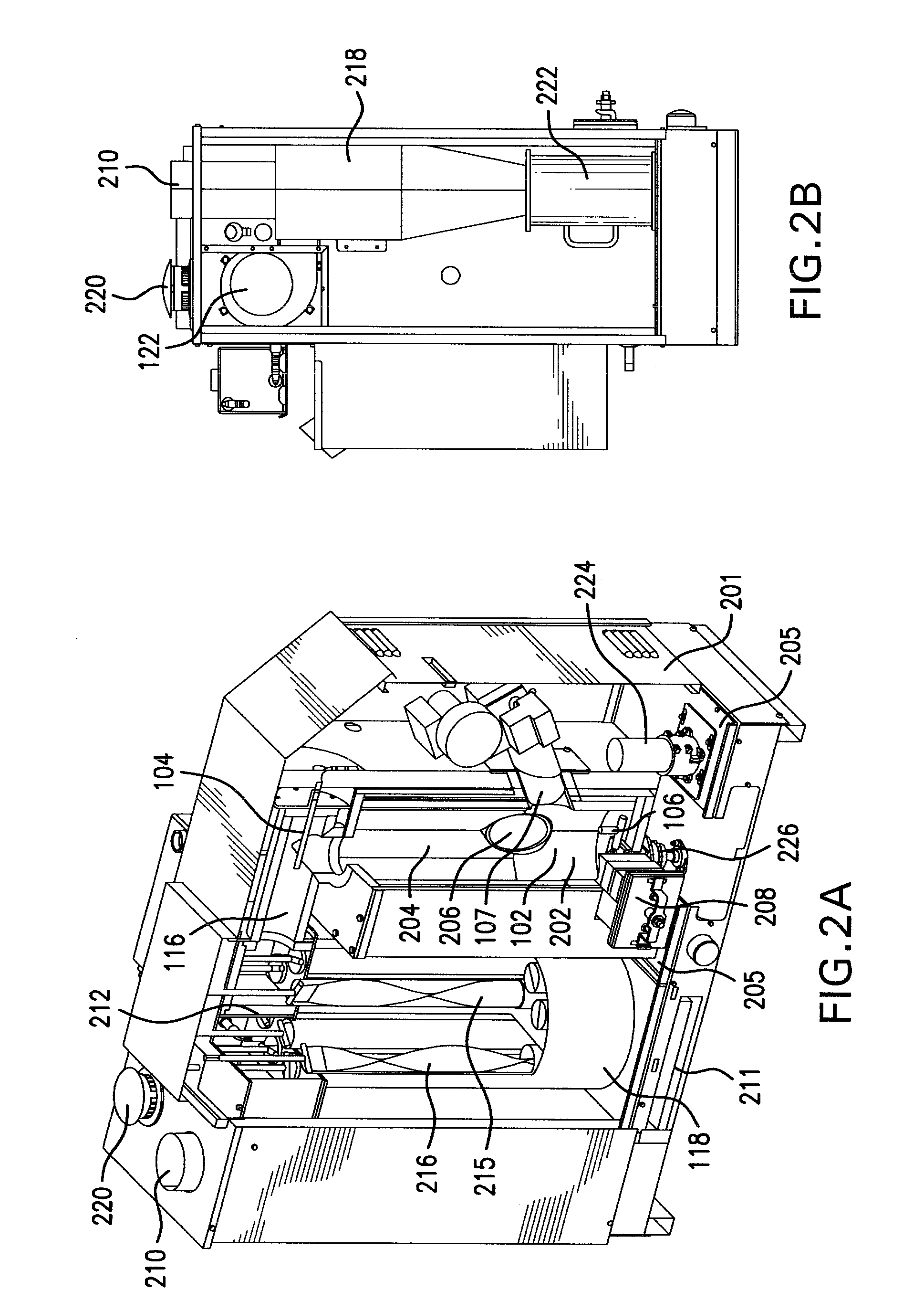
[0032]The present invention relates generally to a non-catalytic multi-fuel burner (or stove) having improved efficiencies and methods of operation. Heat energy is created by burning either traditional or non-traditional biofuels inside a combustion chamber of the burner. Tra...


PUM


Abstract

The present invention relates to a non-catalytic biomass burner that may be used to burn a variety of fuel types at high efficiencies. The burner may include a cylindrical combustion chamber with an auxiliary igniter to heat the fuel in the combustion chamber until desirable combustion temperatures are reached. Fuel may be added to the chamber via a fuel feed assembly, and the rate of fuel addition to the chamber by the fuel feed assembly may be controlled by a computer. A fan located on the distal side of a flue pipe from the chamber may also be provided that pulls air into the chamber through one or more air inlets that are designed to encourage cyclonic air and exhaust flow in the chamber. Methods are further provided for controlling the manner of operation of the burner by a computer that may be instructed by a computer program code.

Description

CROSS-REFERENCE TO RELATED APPLICATIONS[0001]This application claims benefit of priority to U.S. Provisional Patent Application No. 61 / 563,921 filed on Nov. 28, 2011, the entire contents and disclosure of which are incorporated herein by reference.BACKGROUND[0002]1. Field of the Invention[0003]The present invention relates to biomass burners and more particularly to an apparatus and method for non-catalytic biomass burning.[0004]2. Related Art[0005]In the United States, the Environmental Protection Agency classifies bio-mass burners into two categories: catalytic burners and non-catalytic burners. The two different types of stoves (or burners) are regulated differently and have different operating requirements. A catalytic wood stove uses a catalytic combustion device to heat, ignite and burn off the smoke generated by the fire. In general, this results in maximum “use” of the fuel (e.g., wood), even and steady production of heat, and very minimal output of smoke and pollutants. The...

Claims


Application Information

Patent Timeline
IPC IPC(8): F23N1/02F23L5/02F23H9/00F23K3/14
CPCF23N1/02F23N2033/04F23L5/02F23H9/00F23K3/00F23L17/005F23N1/022F23B40/00F23B90/02F23K2203/103F23K2203/202F23M2900/05004F23N2025/10F23N2025/19F23N2027/02F23K3/14F24B1/024F24B1/028F23N2225/19F23N2225/10F23N2227/02F23N2233/04Y02B40/00
Inventor LASKOWSKI, SCOTTBAUGHMAN, TIMOTHYDUERICHEN, JOHANNLASKOWSKI, DONALD
Owner LASKOWSKI SCOTT
Why Eureka
Try Eureka