Electric power steering system

Inactive Publication Date: 2013-05-30
JTEKT CORP
View PDF3 Cites 25 Cited by
  • Summary
  • Abstract
  • Description
  • Claims
  • Application Information

AI Technical Summary

Benefits of technology

[0008]The invention provides an electric power steering system that is able to accurately adjust a backlash and t

Problems solved by technology

Therefore, it is difficult to form the bearing hole.
Therefore, there is a possibility that the backlash will no

Method used


Image

  • Electric power steering system
  • Electric power steering system
  • Electric power steering system

Examples


Embodiment Construction

[0016]Hereinafter, embodiments of the invention will be described with reference to the accompanying drawings.

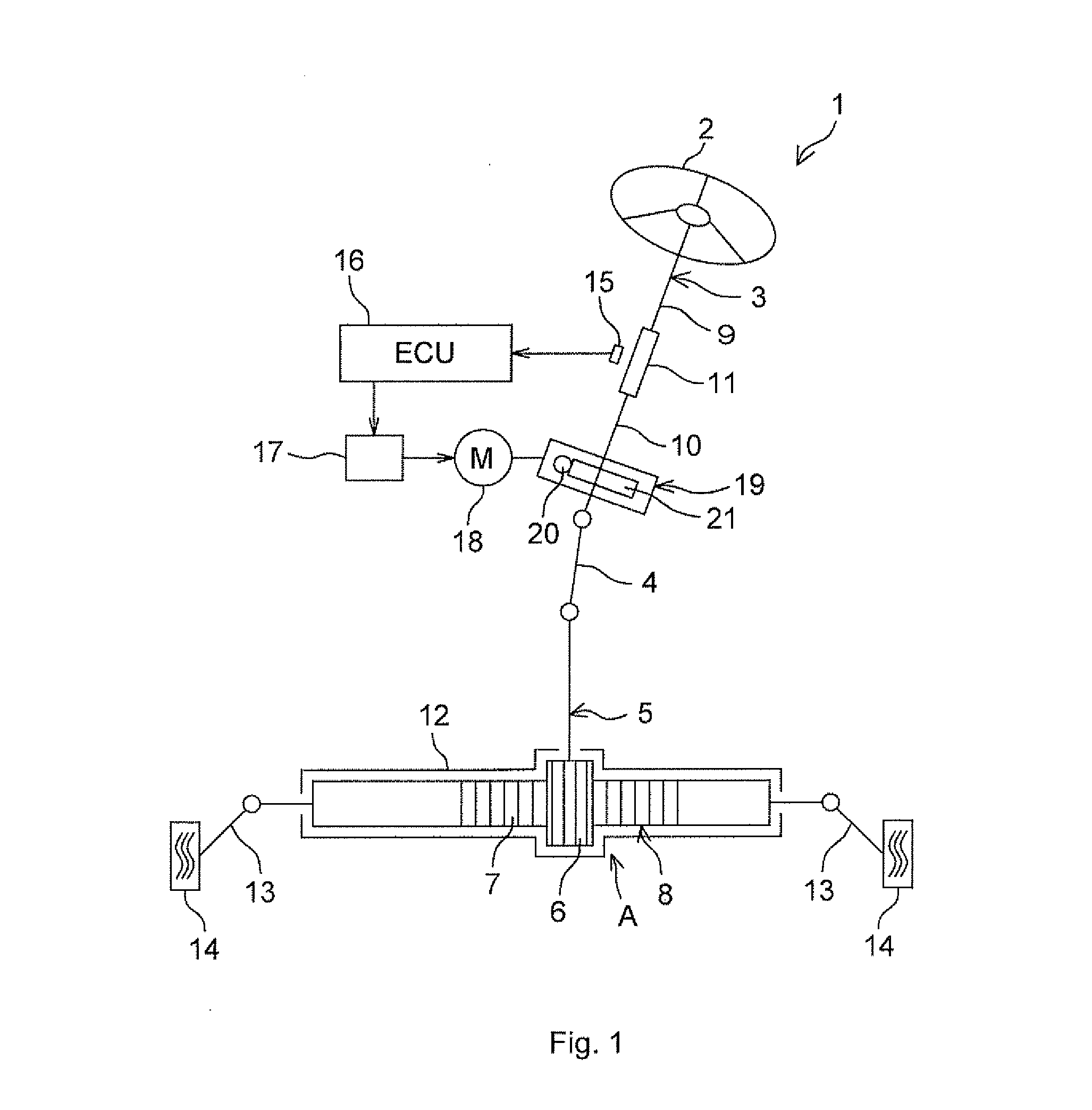
[0017]FIG. 1 is a schematic view that shows the schematic configuration of an electric power steering system 1 that includes a worm reducer 19 according to an embodiment of the invention. As shown in FIG. 1, the electric power steering system 1 includes a steering shaft 3, a pinion shaft 5 and a rack bar 8. The steering shaft 3 is coupled to a steering member 2 such as a steering wheel. The pinion shaft 5 is coupled to the steering shaft 3 via an intermediate shaft 4. The rack bar 8 has a rack 7 that is in mesh with a pinion 6 formed in the pinion shaft 5, and serves as a steered shaft that extends in the lateral direction of an automobile. The pinion shaft 5 and the rack bar 8 constitute a rack-and-pinion mechanism A that serves as a steering mechanism.

[0018]The steering shaft 3 is formed of an input shaft 9 coupled to the steering member 2 and an output shaft 10 coupled to...


PUM


Abstract

There is provided an urging mechanism that elastically urges a second end portion of a worm shaft that is supported so as to be pivotable about a first end portion. The urging mechanism is configured to adjust a backlash between the worm shaft and a worm wheel by elastically urging the second end portion in a perpendicular direction that is perpendicular to a direction in which an inter-axis distance between the worm shaft and the worm wheel increases and decreases, in a state where increases and decreases in the inter-axis distance is prevented.

Description

INCORPORATION BY REFERENCE / RELATED APPLICATION[0001]This application claims priority to Japanese Patent Applications No. 2011-257993 filed on Nov. 25, 2011 and No. 2012-196868 filed on Sep. 7, 2012 the disclosure of which, including the specification, drawings and abstract, is incorporated herein by reference in its entirety.BACKGROUND OF THE INVENTION[0002]1. Field of the Invention[0003]The invention relates to an electric power steering system.[0004]2. Discussion of Background[0005]Japanese Patent Application Publication No. 2010-116090 (JP 2010-116090 A) describes a worm reducer that includes inter-axis distance reduction urging means and lead angle correction urging means, as urging means for urging a bearing that supports a worm shaft toward a bearing hole portion. The inter-axis distance reduction urging means reduces the inter-axis distance between the worm shaft and a worm wheel. The lead angle correction urging means urges the bearing in such a direction that the lead angle...

Claims


Application Information

Patent Timeline
IPC IPC(8): B62D5/04
CPCB62D5/0403B62D5/0409F16C27/04F16H55/24F16C23/08F16H2057/0213F16C2361/61F16C2326/24
Inventor HAMAKITA, JUNMITSUMARU, MICHITOSHINAGAI, YOSHITOMO
Owner JTEKT CORP
Why Eureka
Try Eureka