Electric power steering system

a technology of steering system and electric motor, which is applied in the direction of gearing details, mechanical equipment, hoisting equipment, etc., can solve the problems of inaccurate adjustment of backlash and difficulty in forming bearing holes, and achieve the effect of suppressing steering differences and accurately adjusting backlash

Inactive Publication Date: 2014-08-26
JTEKT CORP
View PDF6 Cites 2 Cited by
  • Summary
  • Abstract
  • Description
  • Claims
  • Application Information

AI Technical Summary

Benefits of technology

[0008]The invention provides an electric power steering system that is able to accurately adjust a backlash and that is able to suppress a difference in the steering feel between steering to the right and steering to the left.

Problems solved by technology

Therefore, it is difficult to form the bearing hole.
Therefore, there is a possibility that the backlash will not be accurately adjusted due to the influence of variations, such as a manufacturing error of each urging means.

Method used


Image

  • Electric power steering system
  • Electric power steering system
  • Electric power steering system

Examples


Embodiment Construction

[0016]Hereinafter, embodiments of the invention will be described with reference to the accompanying drawings.

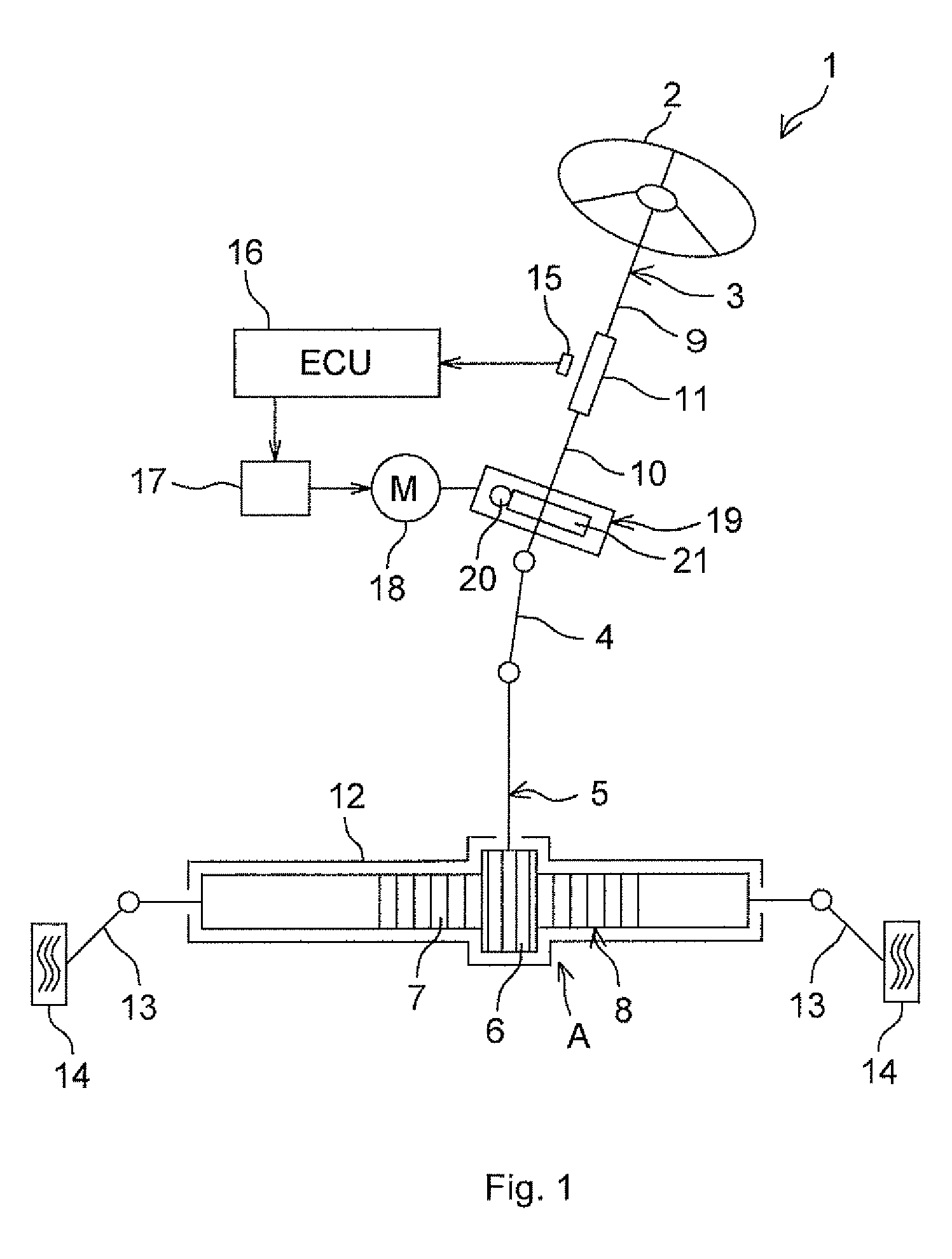
[0017]FIG. 1 is a schematic view that shows the schematic configuration of an electric power steering system 1 that includes a worm reducer 19 according to an embodiment of the invention. As shown in FIG. 1, the electric power steering system 1 includes a steering shaft 3, a pinion shaft 5 and a rack bar 8. The steering shaft 3 is coupled to a steering member 2 such as a steering wheel. The pinion shaft 5 is coupled to the steering shaft 3 via an intermediate shaft 4. The rack bar 8 has a rack 7 that is in mesh with a pinion 6 formed in the pinion shaft 5, and serves as a steered shaft that extends in the lateral direction of an automobile. The pinion shaft 5 and the rack bar 8 constitute a rack-and-pinion mechanism A that serves as a steering mechanism.

[0018]The steering shaft 3 is formed of an input shaft 9 coupled to the steering member 2 and an output shaft 10 coupled to...


PUM


Abstract

There is provided an urging mechanism that elastically urges a second end portion of a worm shaft that is supported so as to be pivotable about a first end portion. The urging mechanism is configured to adjust a backlash between the worm shaft and a worm wheel by elastically urging the second end portion in a perpendicular direction that is perpendicular to a direction in which an inter-axis distance between the worm shaft and the worm wheel increases and decreases, in a state where increases and decreases in the inter-axis distance is prevented.

Description

INCORPORATION BY REFERENCE / RELATED APPLICATION[0001]This application claims priority to Japanese Patent Applications No. 2011-257993 filed on Nov. 25, 2011 and No. 2012-196868 filed on Sep. 7, 2012 the disclosure of which, including the specification, drawings and abstract, is incorporated herein by reference in its entirety.BACKGROUND OF THE INVENTION[0002]1. Field of the Invention[0003]The invention relates to an electric power steering system.[0004]2. Discussion of Background[0005]Japanese Patent Application Publication No. 2010-116090 (JP 2010-116090 A) describes a worm reducer that includes inter-axis distance reduction urging means and lead angle correction urging means, as urging means for urging a bearing that supports a worm shaft toward a bearing hole portion. The inter-axis distance reduction urging means reduces the inter-axis distance between the worm shaft and a worm wheel. The lead angle correction urging means urges the bearing in such a direction that the lead angle...

Claims


Application Information

Patent Timeline
Patent Type & Authority Patents(United States)
IPC IPC(8): B62D5/04F16C23/08F16C27/04F16H55/24F16H57/021
CPCB62D5/0403F16C23/08F16H55/24F16C27/04B62D5/0409F16H2057/0213F16C2361/61F16C2326/24
Inventor HAMAKITA, JUNMITSUMARU, MICHITOSHINAGAI, YOSHITOMO
Owner JTEKT CORP
Why Eureka
Try Eureka