Methods and apparatus for suspending vehicles

a technology for suspension devices and vehicles, applied in the direction of shock absorbers, steering devices, cycle equipments, etc., can solve the problems of not linear, affecting the spring rate,

Active Publication Date: 2013-05-30
FOX FACTORY
View PDF4 Cites 23 Cited by
  • Summary
  • Abstract
  • Description
  • Claims
  • Application Information

AI Technical Summary

Problems solved by technology

While compressed gas springs are usually lighter and more compact than their mechanical counterparts, the compression and expansi

Method used


Image

  • Methods and apparatus for suspending vehicles
  • Methods and apparatus for suspending vehicles
  • Methods and apparatus for suspending vehicles

Examples


Embodiment Construction

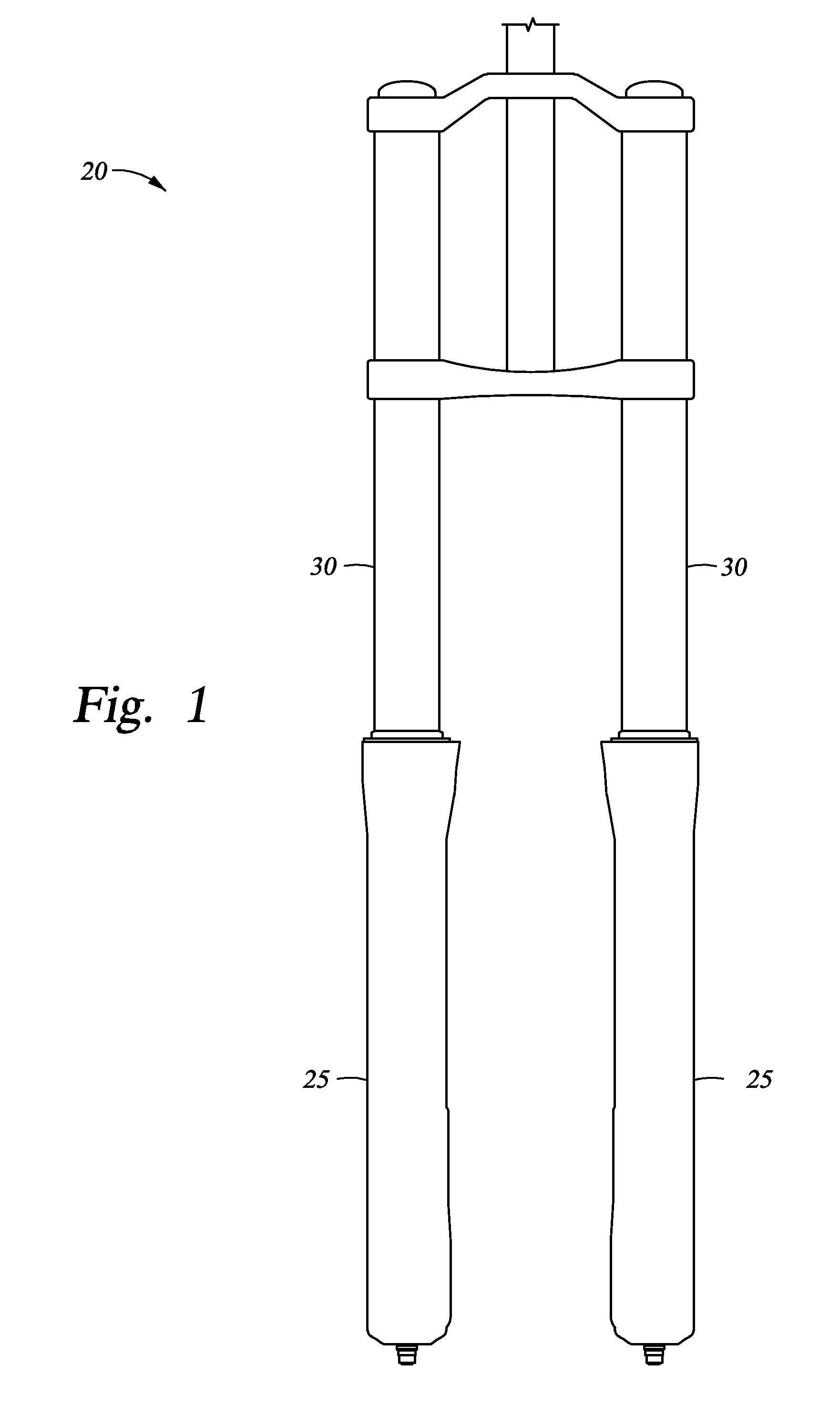
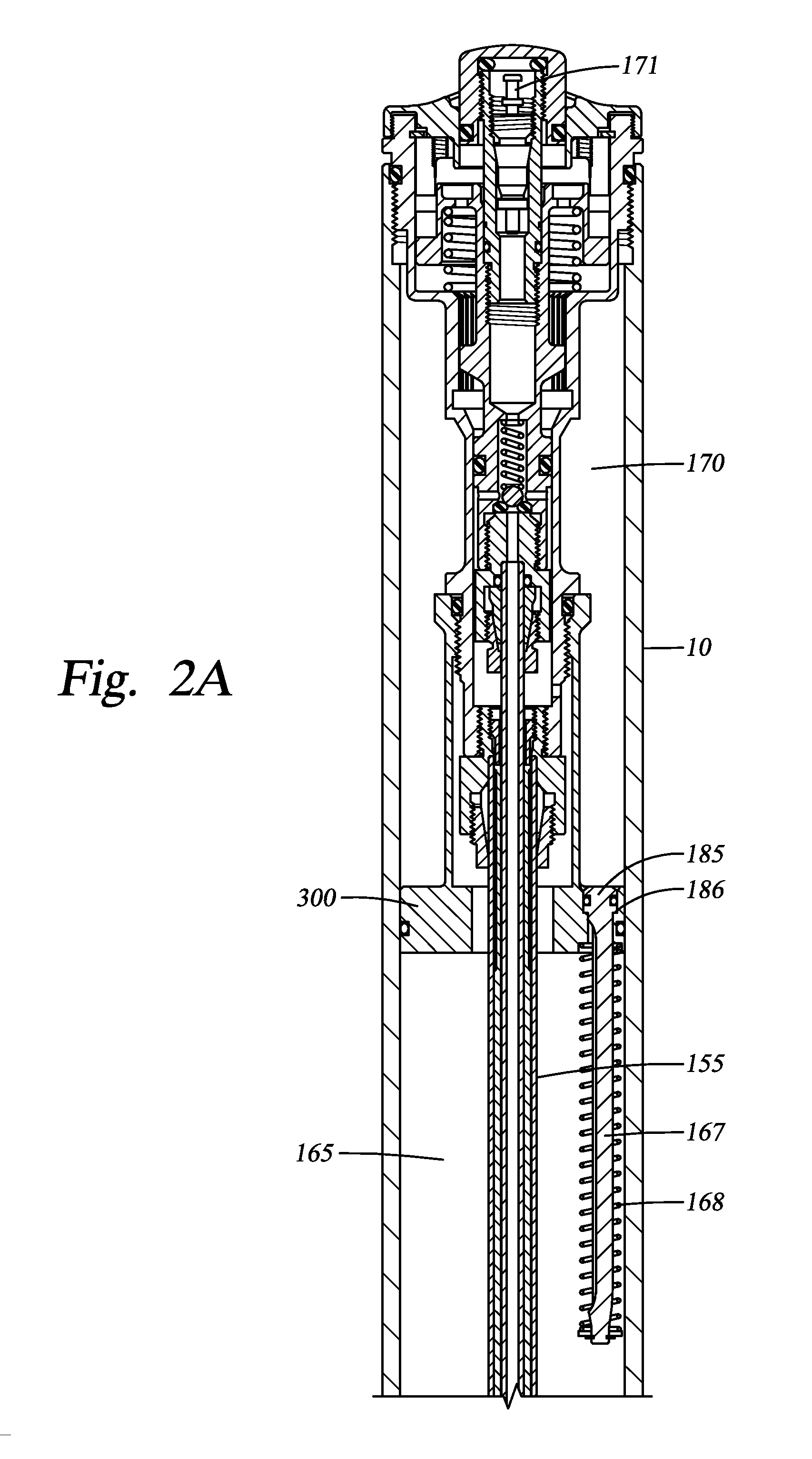
[0016]In this disclosure the term “air” is used interchangeably with the term “gas” unless otherwise stated. Both terms generally indicate a compressible fluid. One embodiment comprises an air spring shock absorber for a vehicle. In one embodiment the vehicle is a bicycle. In one embodiment the shock absorber is a bicycle or motorcycle front fork leg. The terms “shock absorber” and “front / leg” will each include all terms and unless an embodiment is expressly excluded, embodiments hereof are equally applicable to all. The air spring is advantageous because it includes at least two sequentially activated gas spring chambers that operate to increase the effective gas volume of the spring, at least one communication valve for opening a fluid flow path between the chambers, and a fill valve for selectively applying gas pressure within the chambers. In one embodiment, the fluid path between the chambers is opened using a mechanically actuated valve and in another embodiment, a diameter ch...


PUM


Abstract

A method and apparatus for a shock absorber for a vehicle having a gas spring with first and second gas chambers, wherein the first chamber is utilized during a first travel portion of the shock absorber and the first and second chambers are both utilized during a second portion of travel. In one embodiment, a travel adjustment assembly is configured to selectively communicate a first gas chamber with a negative gas chamber.

Description

BACKGROUND OF THE INVENTION[0001]1. Field of the Invention[0002]Embodiments of the invention generally relate to methods and apparatus for use in vehicle suspension. Particular embodiments of the invention relate to methods and apparatus useful for variable spring rate and / or variable damping rate vehicle suspension.[0003]2. Description of the Related Art[0004]Vehicle suspension systems typically include a spring component or components and a damping component or components. Frequently those discrete components are separately mounted on a vehicle. Traditionally, mechanical springs, such as metal leaf or helical springs, have been used in conjunction with some type of viscous fluid based damping mechanism mounted functionally in parallel. More recently, compressed gas acting over a piston area has replaced mechanical springs as the spring component in some contemporary suspension systems. While compressed gas springs are usually lighter and more compact than their mechanical counterp...

Claims


Application Information

Patent Timeline
IPC IPC(8): B60G17/052B62K25/08
CPCB60G2500/22B60G17/048B60G2202/152B60G17/052B62K25/08B60G2600/21F16F9/063B60G2300/12B60G2500/2064F16F9/486F16F9/0209F16F9/0236F16F9/46F16F9/48B60G11/27
Inventor LAIRD, ANDREWPELOT, SANTE M.BECKER, WILLIAM M.WOOTTEN, DENNIS K.
Owner FOX FACTORY
Why Eureka
Try Eureka